
-
-
Be careful when dealing with the magnets. If you are not careful and those snap back together, you'll most likely end up with a broken magnet.
-
-
-
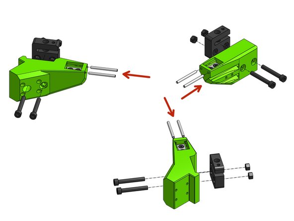
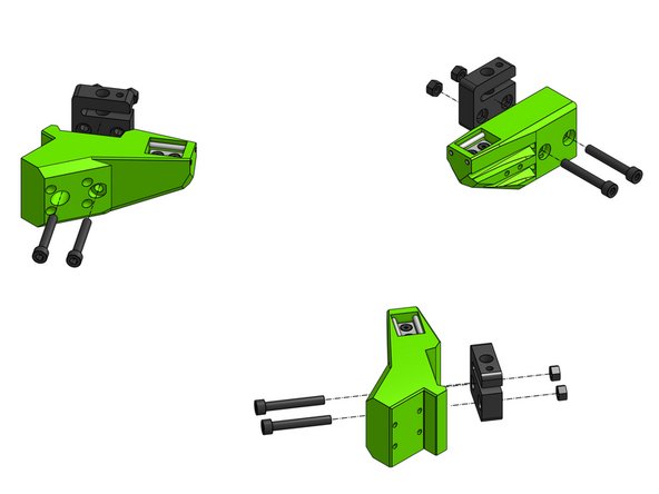
Most of the steps repeat for all of the arms, others are repeated for the front arms and there's a special step for the back arm
-
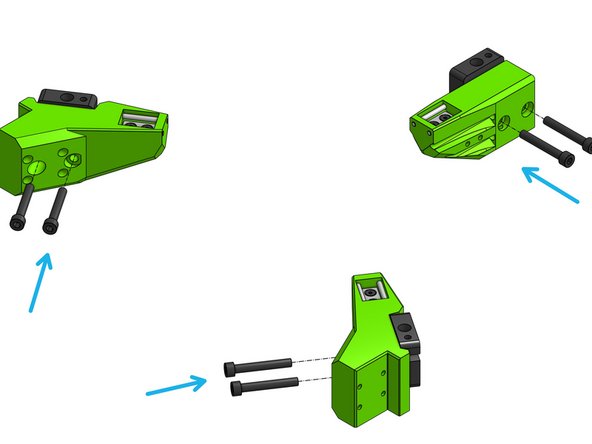
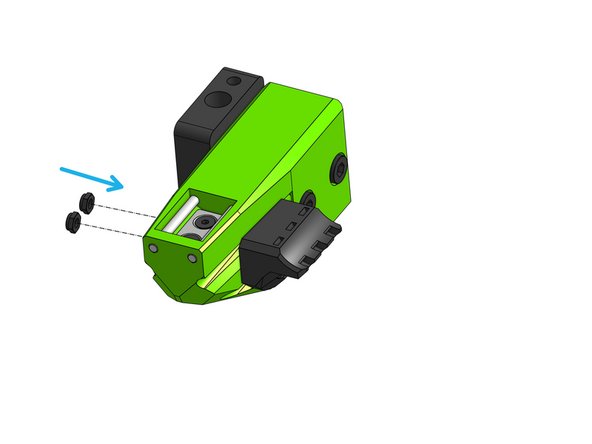
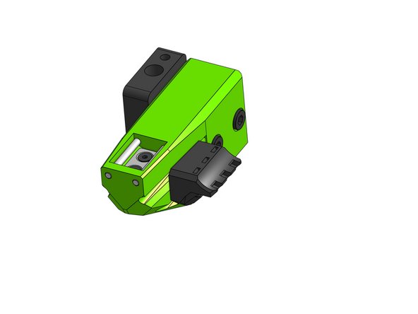
Fit the magnets in the bed arms and drop the Countersink Screws M3x20 through the magnets and printed parts
-
Fasten the magnets by attaching 2x M3 hex nuts from the bottom of each arm
Keep the three 5mm adjustment screws (AKA grub screws) and the three 5mm square nuts that come in the package with the nut blocks. These may be needed on your printer in the future to mitigate Z wobble by turning these nut blocks into anti-backlash nuts. They will not be installed or adjusted in this build guide. These items may be needed when you are tuning your printer.
Paul Largent - Resolved on Release Reply
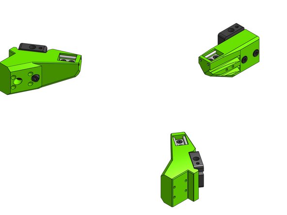
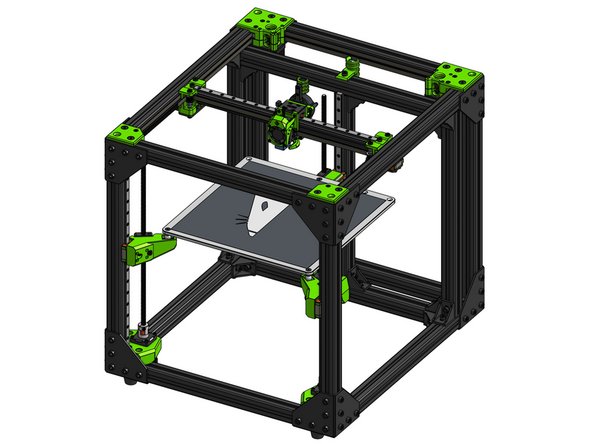
Ignore the lead screw nut blocks shown in this graphic. They will be attached in step 4.
Paul Largent - Resolved on Release Reply
-
-
-
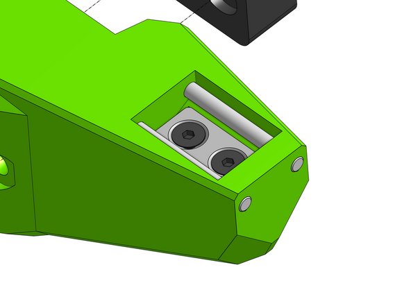
Each bed_arm takes 2 3mm x 35mm dowels. Gently press or twist the dowels into the holes.
-
Be careful not to crack the part!
-
There are many easy ways to do this safely - using force is not one of them. "Screwing" those in as one would a screw is a good practice, you can even use a drill on low RPM to push them in.
pre-drill the hole before inserting the pin is a option, just dont over drill the hole so the pins get loose. Otherwise you can “melt the hole” and lock the pins into the part.
Since we work with thermoplastics that is a neat property of them… melting where it is nesessary. We use a solder-iron. Glue is an option but we prefer “ironing”
i filed a point onto the end of each dowel and tapped them in with a hammer without issue, The point allowed the location of the hole at the back of the block. The pins went in slightly off parallel and the point allowed the dowel to find the hole and centre itself
mark von kanel - Resolved on Release Reply
Ignore the lead screw nut blocks shown in this graphic. They will be attached in step 4.
Paul Largent - Resolved on Release Reply
To perform the power drill method of inserting the dowels: Insert a dowel approximately 3mm into the chuck of a power drill. Tighten the chuck around the dowel with gentle pressure. Activate the power drill on its lowest RPM setting. Gently guide the spinning dowel into its hole and apply gentle pressure. The dowel should go through the outer hole, then above the magnet and start into the second hole. Stop the drill before the drill chuck contacts the plastic part. Finally, apply pressure to the end of the dowel so it will slip further into the printed part until it is flush with the printed part.
Paul Largent - Resolved on Release Reply
-
-
-
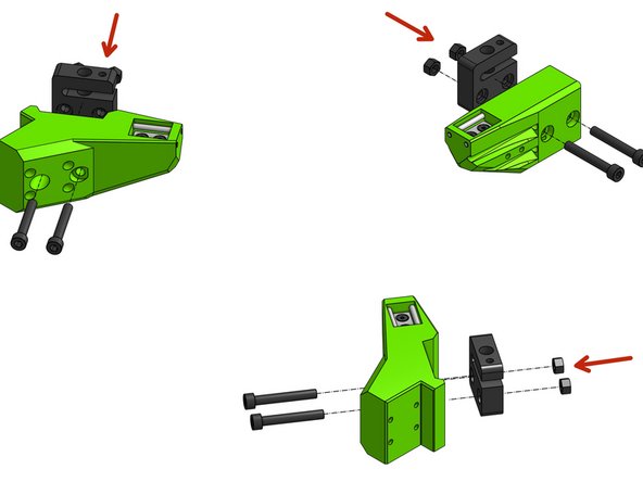
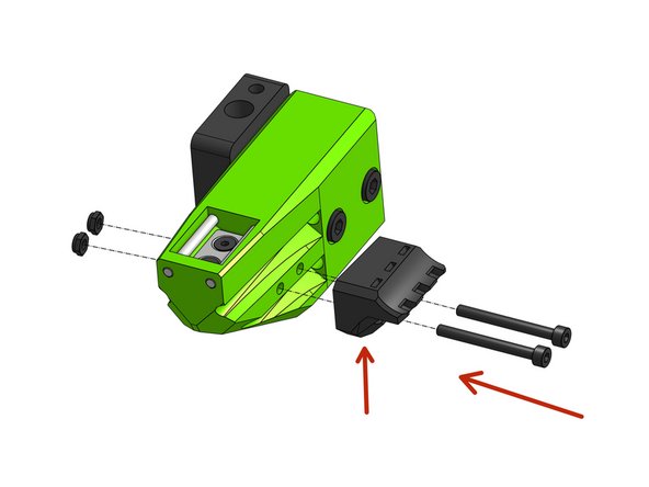
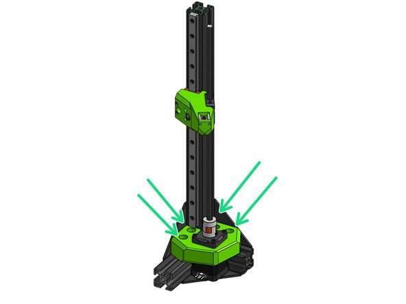
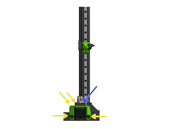
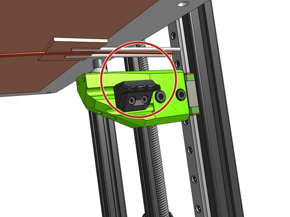
Put the M5 hex nuts into the blocks
-
Fasten the blocks by threading Cap Head Screws M5x35 through the plastic parts
-
Make sure those are secure and not moving but ensure there is no pressure from the screw tension on the blocks - those are made of a soft plastic, that when squished will bind the lead screw
I found that overtightening the lead screw nuts to the arms leads to much more torque required to rotate the lead screws (even when properly aligned). My opinion is that the lead screw nuts should only be gently tightened to the arms. Enough that threads get through the nylon in the locknut and the lead screw nut can’t be shifted out of position by hand, but no more than that. Try over tightening beyond that and compare the torque required to turn the lead screws and you can feel when you’ve gone too far.
The lead screw nut blocks may appear to have different orientations with respect to the bed_arms. The orientation shown in the graphic always has the side of the nut block with two holes on the same side of the plastic bed_arms as the magnet. These two holes will be facing upwards towards the bed when the bed is placed on the bed_arms in a later step. The opening (gap) in the nut block may point toward the magnet or away from the magnet. The nut blocks will extend above the bed_arms but they will not interfere with the bed when the printer is operating.
Paul Largent - Resolved on Release Reply
The lead screw nut blocks have two sides. One side has a hexagonal recess to accept the 5mm locking nuts. Press the locking nuts into these recesses before mounting the nut block to the bed_arms. The “Pulling nuts from the back“ technique described in section 00 works well here.
Paul Largent - Resolved on Release Reply
-
-
-
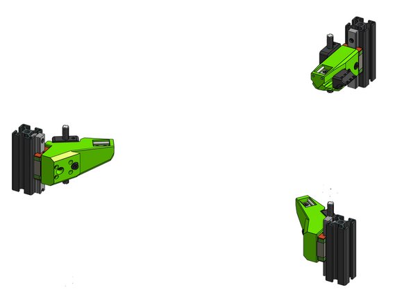
Thread each arm on its respective lead screw (loosening the lead screw in it's coupler might help here)
-
Attach the arms to the MGN carriages with 4x Cap Head Screws M3x20 for each arm
It is advisable to pull the nuts in from the back on the back arm in order to be able to perform the next step.
Flip Breukers - Resolved on Release Reply
This step has us putting arms on lead screws but i dont see step where lead screws were told to be installed
David Westendorf - Resolved on Release Reply
This has been fixed in this documentation. Attaching the lead screws is performed later and this step is now about “attaching the arms” to the frame. Ignore the lead screws that appear in the graphic of this step.
I suggest swapping step 5 and 6… do 6 first… then 5. step 5’s picture shows step 6 already done btw.
Daniel Moran - Resolved on Release Reply
This swap has occurred in this documentation. You can now “attach the arms” in this step and “attach strain relief” in the next step as David and Daniel suggested.
-
-
-
Thread the Cap Head Screws M3x30 through the bed_cable_relef part and attach it to the arm part
-
Insert the M3 hex nuts in the slots on the other side and pull them in by screwing in the screws - this will ensure those are aligned properly and not bind in the part.
Here too the “Pull the nut in from the back“ is advisable. Can be done before the arm is attached to the frame.
Flip Breukers - Resolved on Release Reply
This cable strain relief will accept three nylon wire ties in the future. They each go in one of the rectangular holes, curve 90 degrees inside the plastic strain relief and then come out another rectangular hole. Now is a good time to run a small wire tie through each of these holes to make sure they are properly cleaned out.
Paul Largent - Resolved on Release Reply
It’s not possible to slide the M3x20 (next step) in behind the cable strain relief. Instructions would be better to suggest to locate everything but leave the tightening till after the arm is attached to the rail.
This problem has been fixed. What used to be the next step (attach the arms to the frames) now happens before this step.
-
-
-
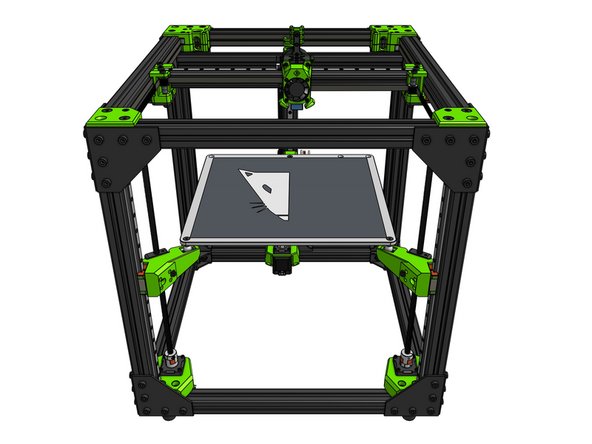
The goal here is to ensure the lead screws are paralel to their rails. This step is very important to ensure proper print quality. The Z motor mounts were designed to allow some adjustment - we'll take advantage of that here
-
If needed loosen the 4 screws holding the front motor mounts and move the motor around to achieve proper lead screw alignment
-
Proper alignment is when the arm does not bind in any point
-
Ensure the alignment of the back lead screw by allowing the mount to move in X with the M5 screws
-
Alignment in Y of the back lead can be achieved by loosening of the M3 screws holding the motor to the mount
-
If you did not already, at this point make sure to fasten all screws in the MGN rails
-
Please refer to the linear rail installation guide for instructions on the correct order to fasten the cap head screws
The easiest and most certain method of achieving alignment and smooth operation recognises that the tops of the screws float. This means that the constraints are the travelling arms (not adjustable) and the motor mounts (adjustable).
Try this
1) Release the four M6 screws fastening the motor bracket to the frame for each motor. The base of the lead screw is now adjustable in the X-Y plane.
2) Wind the lead screws through the nuts. Wind enough through so that the screw can be fully inserted into the coupler. Tighten the coupler capture screw.
3) Rotate the lead screws to move the travelling arms down to make light contact with the coupler. Move the motor mounts around to allow that travel to the point of contact. The motor and the lead screw nut are now aligned.
4) Wind the screws to move the travelling arms up and down 100 mm or so to confirm that travel is free and unrestricted.
5) Tighten the motor mount M6 screws.
6) Wind the arms up to the top (minimum z) to confirm that all is well.
Vernon Yates - Resolved on Release Reply
Adam from Vector3D kindly maid some Jigs to make the alignment of the lead screws easier. They work great! Can be found here:
The Jig from Adam works perfect.
The two front lead screws fell in without any adjustment. The back one though. There was no room for wiggling the complete motor carriage (bottom plate was a snug fit. Luckily the stepper motor mount had just enough wiggle space to adjust it the 0.5 mm it needed to fit in the coupler.
This step now starts by: Installing the three lead screws through the lead screw nuts. This is done by screwing the lead screw into the lead screw nut from above. The lead screw will first go through the top of the lead screw nut and continues below the lead screw nut. The lead screw is then inserted into the motor coupler that was previously attached during the “motor mounts” section. It should make solid contact with the bottom of the coupler. The grub screw on the coupler is then used to tighten the coupler to the lead screw. The lead screw should now spin about the axis of the motor and the axis of the coupler. The rest of this step is to ensure that the lead screw is parallel to the rail so the bed arm moves strait up the rail without sideways movement (X axis or Y axis) as it goes from the bottom to the top.
Paul Largent - Resolved on Release Reply
Now is a good time to double check that the Z rails are not touching the motor mounts. You put them 1 or 2 mm above the motor mounts in a previous section.
Now is a good time to double check that each of the three 3030 extrusion involved goes strait up and are perpendicular to the bottom of the frame where they are attached. If they are not close to going straight up then it will be difficult or impossible to complete the alignments in the remainder of this step.
What exactly do you mean when you say “lead screw nut “? I’m not sure which part this is referring to?
The lead screw nut is the plastic threaded piece that screws onto the lead screw at step 4.
get the alignment roughly right, then loosen the screws that hold the lead screw nut and make sure the lead screw is properly aligned with the coupling. Not doing this will drastically reduce the life of both coupling and lead screw nut, and could cause artifacts in the print.
joshua43214 - Resolved on Release Reply
-
-
-
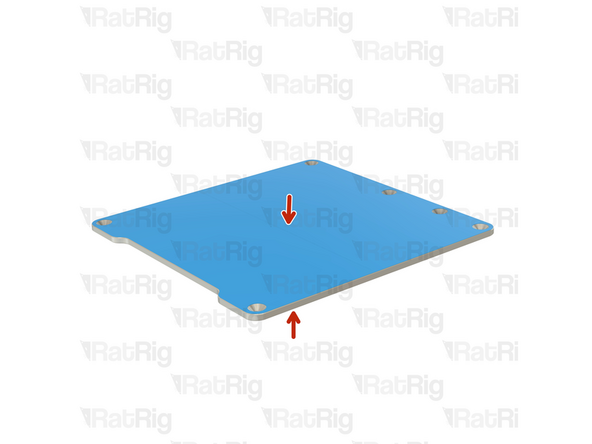
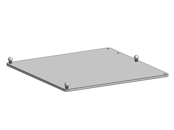
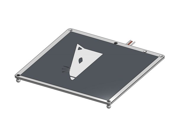
To prevent scratches, the bed plate is shipped with a protective film on both sides.
-
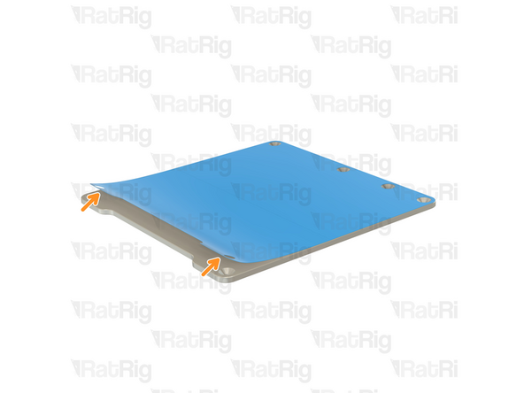
Gently peel off the protective film.
-
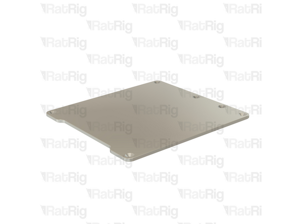
Repeat for the other side.
-
-
-
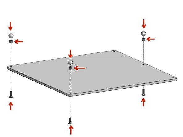
Attach the Countersink M5x16 screws to the 12mm balls through the 6mm spacers
You should add the grounding hardware in this step. For the 500 model, if you center the magnetic bed on the steel plate it partially covers the holes and makes installing the grounding hardware difficult later. Or you could install the magnetic bed so it’s all the way forward on the steel plate to clear the grounding hole. But there is no guidance on where to stick it other than the photos which show it centered, so I wasn’t sure if off center would be ok.
Remember to remove the plastic film that’s on top of the bed. I nearly installed the heater pad on top of it.
Absolute Prodigy - Resolved on Release Reply
500mm bed doesn’t have it… but ours is from last Feb, so maybe they didn’t when we got ours… finally finishing it now, many months later.
JayM -
I recommend doing this last. If you do this first, you will just be fighting tippy wobble in the next steps.
Attach the magnet to the top first while the plate lays nice and stable. Don’t trim the magnet to fit the holes yet.
Flip over and attach the heater pad, I suggest running a bead of high-temp silicone RTV around the edge to make double sure it does not detach. I also recommend attaching insulating material at this point as well. I used the common mats purchased on Ebay, the balls are tall enough that the mat will clear the arms.
Last, attach the balls, only trim the magnet if you can’t squeeze the screws past it.
joshua43214 - Resolved on Release Reply
-
-
-
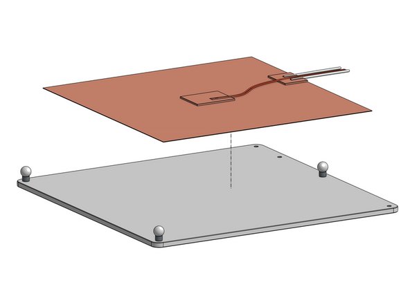
This is a mains voltage element, you should consult an electrician when dealing with it
-
You may want to wipe the surface of the bed with >90% alcohol to make sure you are attaching to a clean surface
-
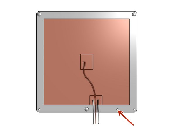
Peel off the sticker's protective layer from the pad and glue it to the bottom of the bed plate
-
The extra hole is there for a ground wire
-
-
-
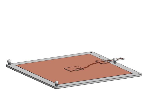
This step depends on the print surface type of your choosing but in general it's always a good idea to clean the surface from any dirt and grease
-
Attach the print surface
The 500 magnetic bed (the black magnetic part) should be installed such that it’s forwardmost edge lines up with the forwardmost edge of the steel bed. Otherwise the Y max endstop will not allow for enough backward (positive Y) adjustment to allow for a full 500mm of Y printing area. Doing this also clears up the mounting hole for the grounding hardware, allowing you to install it later during wiring.
-
-
-
Place the assembled bed on the bed arms
-
Secure the bed wires to the bed_cable_relief part with zip ties
-
Those wires carry mains voltage, you should consult an electrician when handling them
Why is the step with the wormscrees and their counternuts not included in this part and explained what the intention is, as fixing those makes the whole movement stiffer as it was before.
awiltschek - Resolved on Release Reply
-


Cancel: I did not complete this guide.
52 other people completed this guide.

6 Comments
There appear to be some proprietary parts. Any way you folks would consider selling say the bed, magnets, and balls? I'd love to add this set up to my custom printer.
Derrick James - Resolved on Release Reply
The bed is just a standard aluminum tooling plate. They are pretty inexpensive, and available pretty much any place in the world that has industry. Just search the internet for “cast aluminum tooling plate.” Mic6 is the tradename for the Alcoa version (this is the industry standard, buy this if you do not trust yourself to buy something different), but any plate from a reputable supplier will probably be just as good provided it is advertised as being stable. The balls are just threaded steel balls, nothing special, same for the magnets.
I think there needs to be information about when and why to adjust the POM nuts’ tension - in the instructions the adjustment screws are not used/mounted at all…
Hi! Nut tensioning is only required in some edge cases, when the Nut is too loose. By default, you don’t need to apply any tension.
Rat Rig -
This warning is no joke…
I placed them far apart on the table but one slipped out of the part while trying to put the screw in and it jumped rather spectacular over the table right to another magnet. Now I got 4 instead of 2.
Fortunately they broke in a way that I could still screw them in.
LuiAurie - Resolved on Release Reply