
-
-
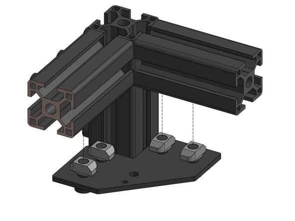
Thread the Cap Head Screws M6x12 through the idler plates. Four screws per plate
-
Attach the 3030 M6 T-nut to the screws. Don't tighten yet
-
-
-
Looking from the back of the printer we will now focus on:
-
The right XY idler
-
The left XY idler
When you turn the front of the printer towards you, Right is on your Right hand side and Left on your Left hand side.
Flip Breukers - Resolved on Release Reply
So you print L & R on the bits and in this description you reverse them! GET REAL!
mark von kanel - Resolved on Release Reply
This view point, from the back of the printer, makes this confusing. Left and right are marked on parts based on front view, not back. The directions should be from that point of view to keep things simple
Daniel Kocian - Resolved on Release Reply
-
-
-
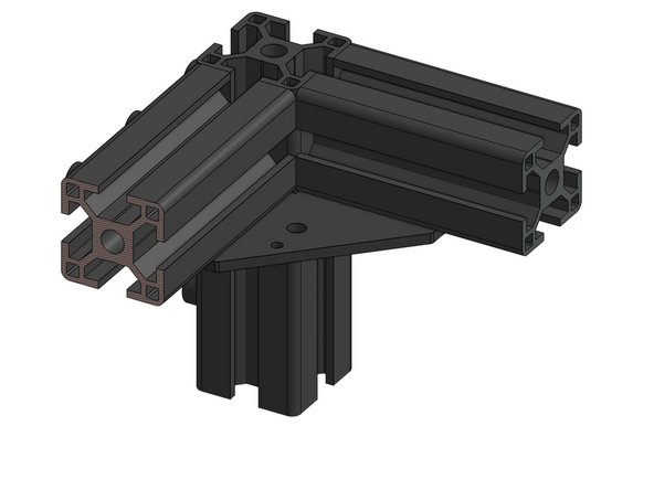
Attach the right XY Idler base to the frame. Fasten the nuts firmly
-
Repeat for the left side
small 2 holes are oriented to the back of the printer. You should state that because it is possible to orientate the holes in the wrong direction easily
David Morgado - Resolved on Release Reply
global view would be appreciated, since I can’t really see where we are and how I should orient the part
Alexandre De Oliveira - Resolved on Release Reply
-
-
-
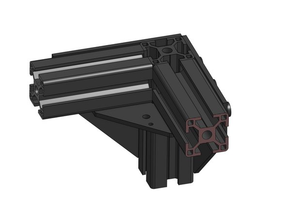
Slide the 3030 M6 T-nuts' into their place in the extrusion
-
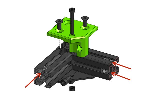
Fasten the xy_idler_right to the frame with the two Countersink Screws M6x14 and one Cap Head Screw M6x12 that goes in from the side
-
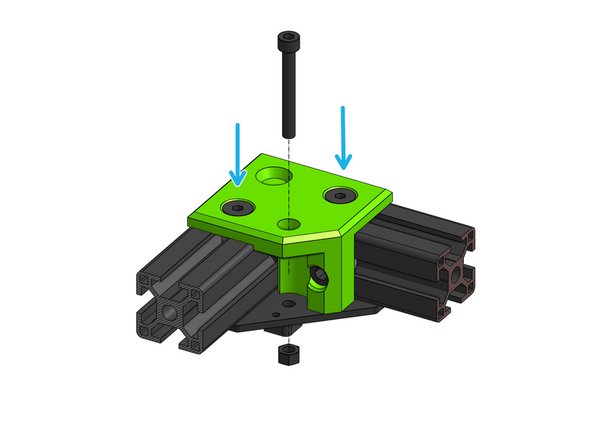
Prepare a Cap Head Screw M5x40 but do not thread it in yet.
I could easily fix the idler to the frame by putting a T-Nut on the M6 x 12 and a T-Nut on the countersunk 6 x 14 which would go into the frame rail going to the back of the printer. With this method you can wiggle the idler in place, then drop a T-nut in the frame rail which spans across both sides and by sliding it gently under the other counter sunk M6 x 14 you can easily fix the idler. Gently fasten the idler. Don’t over tighten it (the idler might crack). Then you can build the stack. I took a spare M5 x 20 or M5 x 30 and pushed it from the bottom up, adding the stack components one by one, then (it’s a bit of a juggle) and guide the belt through the idler. Push the M5 x 40 cap head from to to bottom pushing out the reversed M5, If you guide it gentle the stack remains in place and the M5 x 40 will slide through easily. Bottom nut to fix it and …. done!
Flip Breukers - Resolved on Release Reply
What actually needs doing is the printed idler assay needs altering so that the 5mm hex nut sits on the top. you can then insert the cap screw from underneath and add the components one by one, slowly pushing the cap screw upwards to accommodate each component. i used a spare cap screw to do it this way, i then pushed the permanent cap screw down from the top whilst slowly pulling out the screw id used to stack the assay downwards.
doing it this way took a few mins each side
mark von kanel - Resolved on Release Reply
If it is possible some idiot will do it. I pushed a T-Nut past the hole and it fell down the upright. Then I was turning the frame on its front to get it out and the other nut slid and fell down the upright. Turning the whole thing upside down got them out. Bottom line there are lots of ways to screw this up so be careful.
peter williams - Resolved on Release Reply
Correction: 1) Lay the frame FRONT face down on your work surface so the rubber feet are facing AWAY from you.
Paul Largent - Resolved on Release Reply
Everybody above is right! This is difficult to do in the order described with the orientation shown. This step and the next two (#5 and #6) will go a lot easier if you: 1) Lay the frame FRONT face down on your work surface so the rubber feet are facing the ceiling. This is optional and a bit of work but it makes the next steps easier. 2) Put the plastic XY_Idler_Right part where it belongs but do not tighten the bolts and T-Nuts yet. 3) Put the 5x40mm long bolt through the plastic and then place the shims, spacers and idlers on the bolt. It helps to have a second bolt coming from the other site while adding these parts in the space between them. 4) Push the long bolt through the metal bracket and attach the 5mm lock nut on the 5mm bolt loosely. 5) Tighten the 6mm bolts and T-Nuts. 6) Finally, tighten the 5mm bolt and lock nut. Spin the Idler to ensure it spins freely. Then do the Left side in the same order. Finally, put the frame upright again with the rubber feet back on your work surface.
Paul Largent - Resolved on Release Reply
It’s easier to put the T-Nut loosely on the horizontal M6x12, fit the idler to the frame and then slide in the T-Nuts in for the countersunk screws.
Russell Brown - Resolved on Release Reply
Hi Russel, I was just about to comment on this RIGHT now! it seems we are in sinc! You can pre-load the tslots for the cap heap and the countersink to the SIDE of the cap head. This makes it possible to to slide the idler in from the back. Then insert in the tslot for the countersink in FRONT of the cap head when the idler is in place. Its easier to control a loose tslot when its on its back, and you have a good view to align the holes from the top. This would have saved me an hour of frustration!
I strongly suggest, you don’t tighten down the bolts. Not even snug. Else the next steps to put in the iddler stacks are impossible. Wait untill the Iddler stack are in place, before you tighten the bolts to the frame.
ratrig@topgun.dk - Resolved on Release Reply
Be careful inserting the Cap Head Screw M6x12 I nearly split the part inserting mine, the fitment is very tight.
morphelan@gmail.com - Resolved on Release Reply
-
-
-
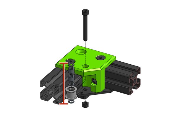
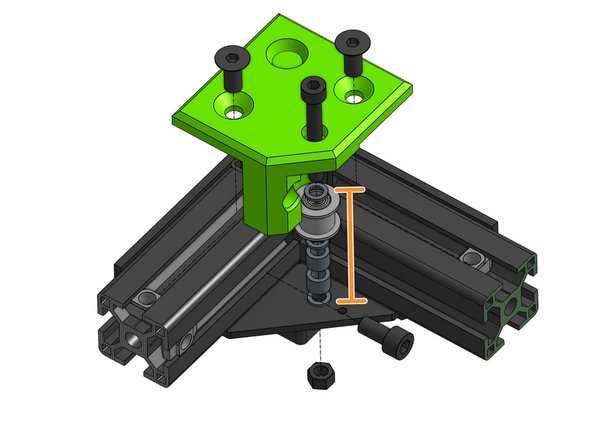
The order for the bearing stack from the bottom is: shim, idler, shim, 2x 6mm spacer, shim
-
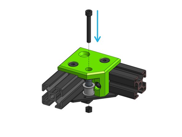
Thread the bearing stack onto the Cap Head Screw M5x40
-
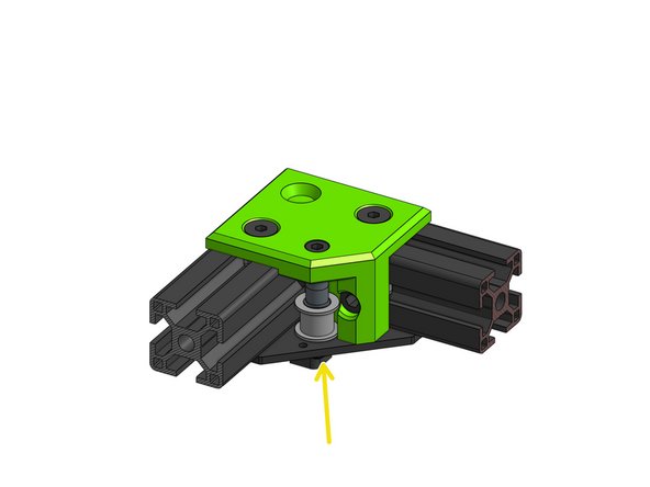
Attach the M5 nut from the bottom, do not over tighten - it should be snug but should not prevent the idler from spinning
If you use one of the M5x55mm bolts from the bottom, you can assembly the entire stack from the bottom up easily. Then drive the M5x40mm down from the top when you have the entire stack completed. Remember to wrap the belt around the pulley when you put it on, since it’s difficult to do after.
Duncan Hord - Resolved on Release Reply
I found it easier to assemble the whole stack of bearings, belt and spacers on the 5 x 40mm bolt (pushed home in the green part) BEFORE fastening the green part to the frame. This way you can steer the bolt into the hole in the lower metal corner piece easily without losing anything in the stackup.
It is relatively easy to push the T-nuts into position afterwards and screw in the 3 main fasteners.
Murray McEwan - Resolved on Release Reply
Side Bolt: I had an issue getting the side bolt to engage the T-nut since the nut had a tendency to lay back at an angle. Found a small magnet, attached to the end of an allen key and used that to insert the nut and hold exactly where it needed to be - easy.
Wow, you’re right. Pre-assembly is the way to go. Probably way easier than trying to do it after or turn the frame upside down. I used the Allen key in the hole method and it worked but wasn’t as easy.
Put a thin rod (a 3mm allen key is ideal) through the bottom hole in the mounting plate at 45 degrees. Slide on the shims, idler and spacers in the correct order and then pull down the rod so the top is flush with the top of the stack and rotate into a vertical position. Then push the M5 bolt down into the stack while withdrawing the guide rod.
Russell Brown - Resolved on Release Reply
This is actually really easy if you ignore these terrible instructions. First, like David said, make sure you thread the belt as you assemble. The trick is to assemble the idler stack unpside down on the bench, then invert it onto the printer frame. The shims are easy to control, so only moderate care is needed to keep them in place. A bit of extra finesse, and you can install the sideways t-nut on the bench as well.
joshua43214 - Resolved on Release Reply
I agree with David on that one. A tip for everyone, it’s not easy to stack the pieces so use a flexible rod or straw from underneath to align the idler pulley washers and spacers as you insert the 40mm m5 bolt. I used a straw from an air duster and it worked a treat.
morphelan@gmail.com - Resolved on Release Reply
When you do this, loop the lower belt, smooth side towards the idler, around the idler before you put it onto the bolt. It is very difficult to thread it after everything is done up.
David Reidy - Resolved on Release Reply
-
-
-
Repeat the same steps for the left XY Idler assembly.
-
The only difference (aside from it being mirrored) is that the bearing stack is upside down - from the bottom it's: shim, 2x 6mm spacers, shim, idler, shim
For some reason, my left stack is too tight to spin while my right stack is just fine. Anyone have any similar issues or recommend any solutions? Considering using a razor to give the printed whole a slight bevel, but looking for better input first.
For anyone else experiencing this issue, I just found a solution. Slowly carve away at the hole on the plastic by gently hand-twisting a drill bit over it. This took some trial and error, removing and reinstalling, but ultimately I think my left idler now moves smoother than the right! Maybe I will notice some issues when I get to printing, but if all seems well I will probably do this to the right idler cap as well.
Brandon -
Does the upper belt go on the left idler and lower belt on the right idler?
James Andros - Resolved on Release Reply
When you do this, loop the upper belt, smooth side towards the idler, around the idler before you put it onto the bolt. It is very difficult to thread it after everything is done up.
David Reidy - Resolved on Release Reply
There’s a small gap for the idler assembly which makes the idler be able to move up and down a little bit. Right side stays in it’s place whereas left one is free to move. It’s not a lack of tighten, I thin the printed part is longer on this side as I measured with the calipper and it’s 0.2 longer on the organge mark in picture above than on the right side.
Pedro Sánchez - Resolved on Release Reply
-
-
-
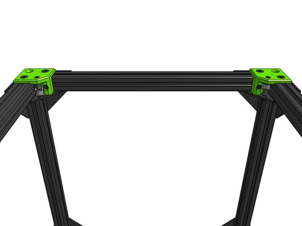
This is how the XY Idler assemblies should look like looking from the back
What do we do with the belts? Should they be threaded through the idlers in this section?
david wilson - Resolved on Release Reply
There is no Information About the belt. When you are new in core xy you forget to do this
Marcel Becker - Resolved on Release Reply
-


Cancel: I did not complete this guide.
50 other people completed this guide.

One Comment
If you are having trouble getting the bearing stack into place, thread the bearing stack onto a thread or a thin wire, then pull the ends of the wire through the holes in the mount, from the inside out. The bearing stack will slide into place.
Tyler Suard - Resolved on Release Reply
Make sure that the 2 different and smaller holes point back towards the electronics bay.
Robert Grabau - Resolved on Release Reply
This picture correctly has the right xy idler assembly on the right and the left xy idler assembly on the left. This is important for the next step in determining which idler goes on the right and left of the frame.
Nick - Resolved on Release Reply