
-
-
19x Heat Insert M3
-
4x vc4_trim_front
-
4x vc4_trim_rear
-
1x vc4_umbilical_frame
-
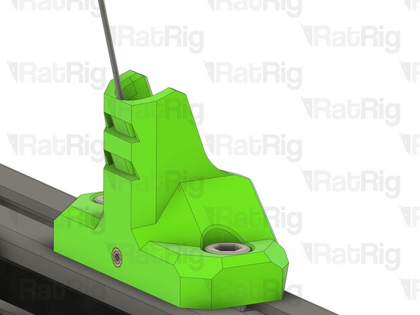
1x vc4_y_endstop_mount
-
-
-
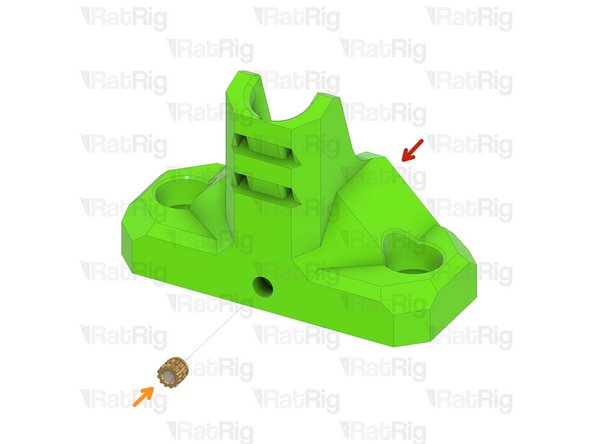
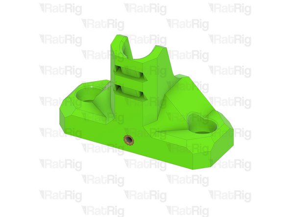
1x vc4_trim_front
-
2x Heat Insert M3
-
Repeat this step until all four parts have the heat inserts in place.
-
-
-
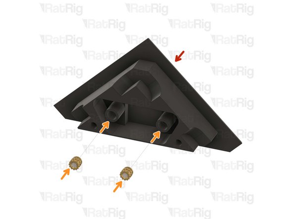
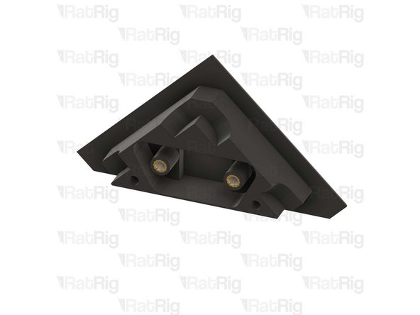
1x vc4_trim_rear
-
2x Heat Insert M3
-
Repeat this step until all four parts have the heat inserts in place.
-
-
-
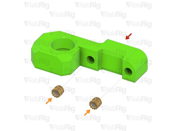
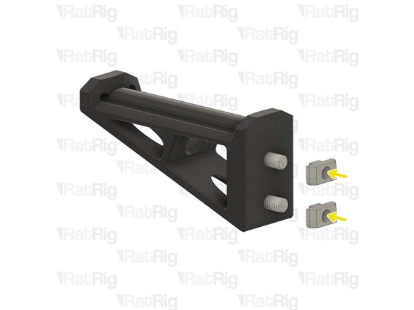
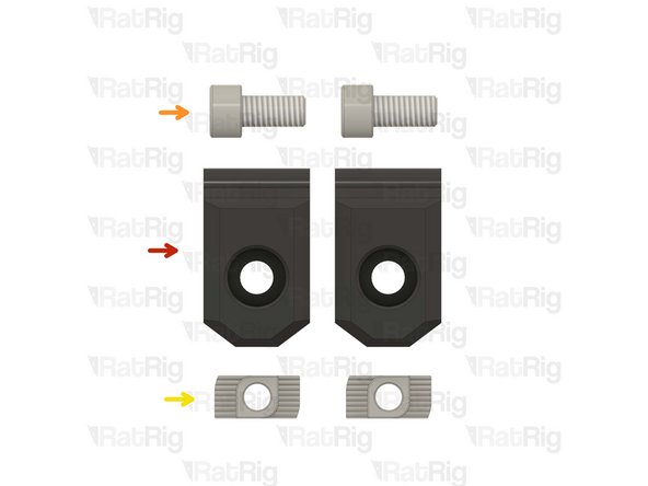
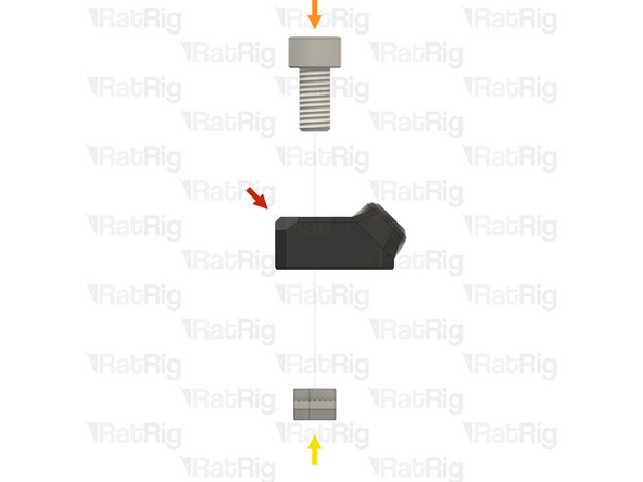
1x vc4_umbilical_frame
-
2x M6x12 Cap Head Screw
-
2x 3030 Drop-in T-Nut - M6
-
1x M3x5 Set Screw
2x M6x12 Cap Head Screw >>>>>>> SKU: HW1836SC
2x 3030 Drop-in T-Nut - M6 >>>>>> SKU: HW1361NC
1x M3x5 Set Screw >>>>>>>>>>>>> SKU: HW3499SC
Vasco Rocha - Open Reply
-
-
-
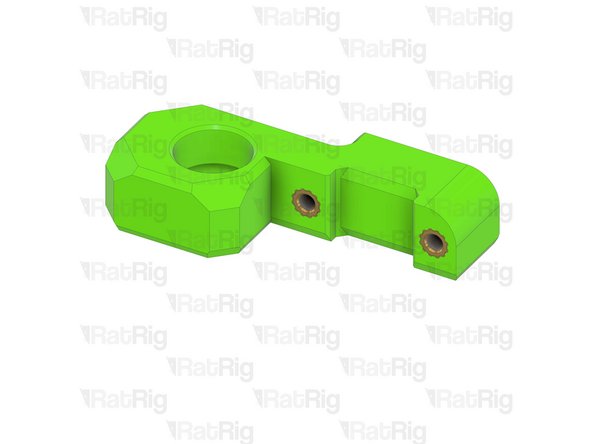
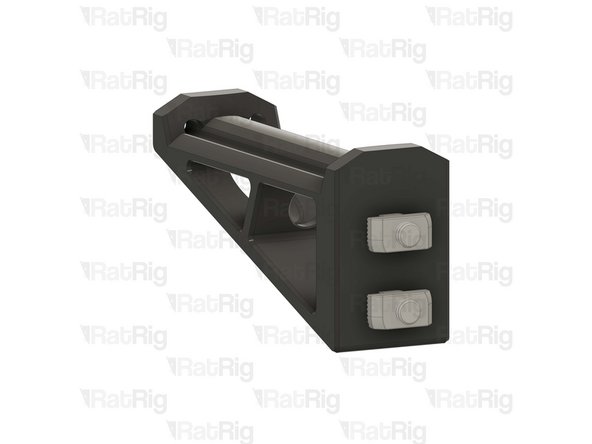
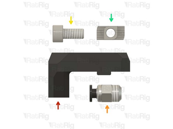
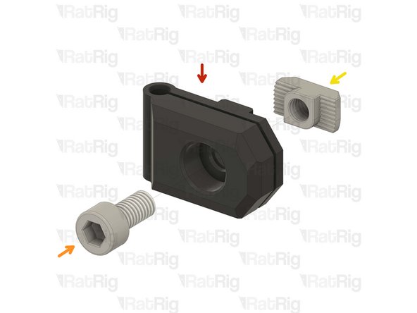
vc4_umbilical_frame
-
2x M6x12 Cap Head Screw
-
Install the M6 cap head screws into the umbilical frame as shown.
-
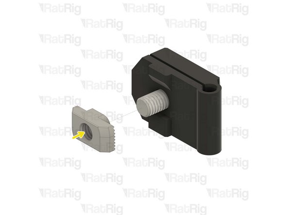
2x 3030 Drop-in T-Nut - M6
-
Loosely thread a 3030 T-Nuts onto the M6x12 screws. Do not tighten it at this point.
-
1x M3x5 Set Screw
-
-
-
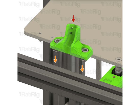
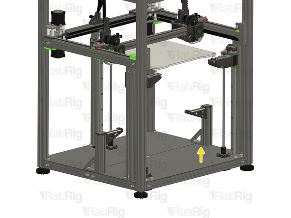
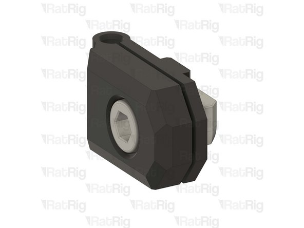
Umbilical frame assembly
-
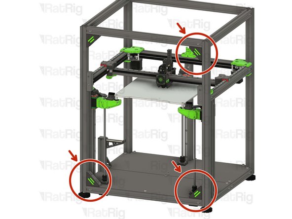
Install the umbilical guide assembly to the V-Core 4 frame as shown.
-
Check that the printed part is seated in the middle of the frame.
-
Tighten the M6x12 screws to secure the umbilical frame.
-
Take care not to over-tighten the M6x12 screws as you can damage the printed parts
-
-
-
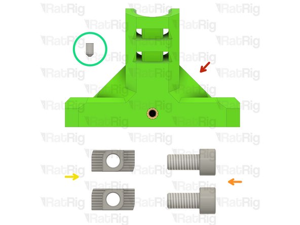
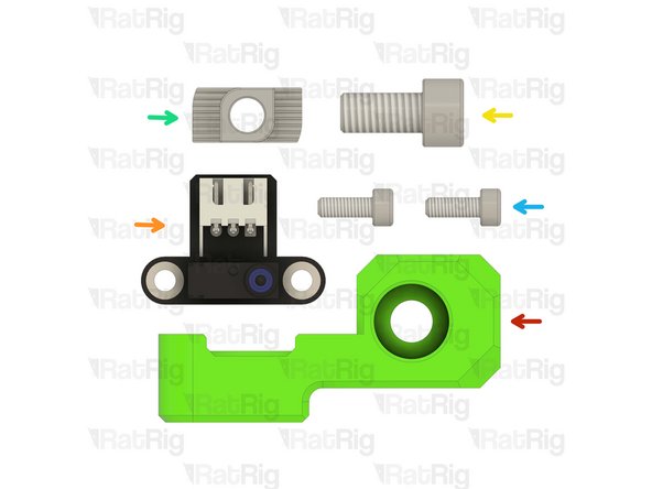
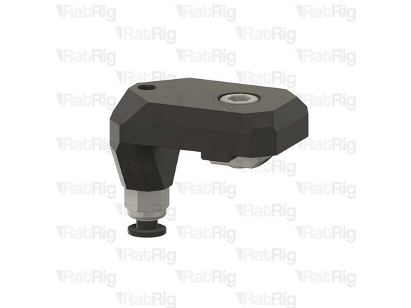
1x vc4_y_endstop_mount
-
1x Rat Rig Endstop
-
1x M6x12 Cap Head Screw
-
1x 3030 Drop-in T-Nut - M6
-
2x M3x8 Cap Head Screw
1x M6x12 Cap Head Screw >>> SKU: HW1836SC
1x 3030 Drop-in T-Nut - M6 >>> SKU: HW1361NC
2x M3x8 Cap Head Screw >>>> SKU: HW1502SC
Vasco Rocha - Open Reply
-
-
-
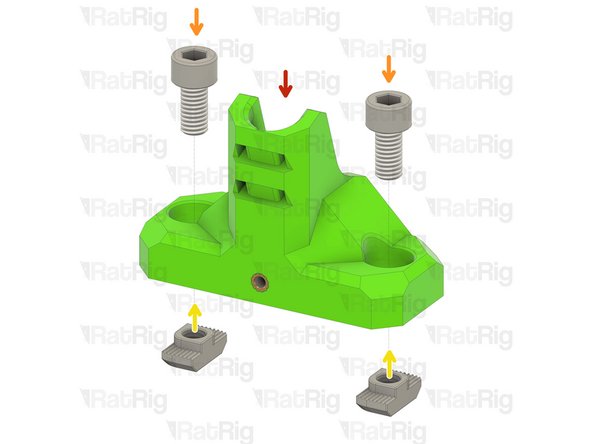
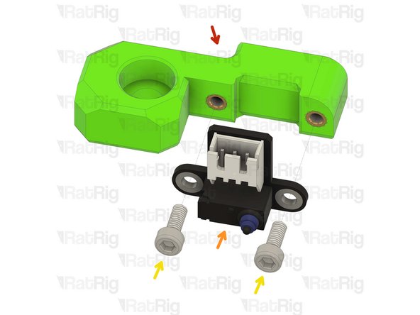
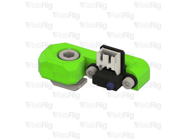
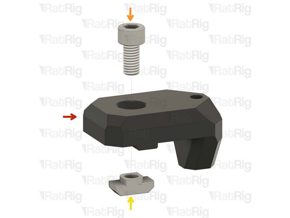
vc4_y_endstop_mount
-
Rat Rig Endstop
-
2x M3x8 Cap Head Screw
-
Tighten the M3x8 screws to secure the endstop to the printed part. Take care not to over tighten as you can damage the printed parts.
-
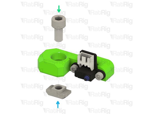
1x M6x12 Cap Head Screw
-
Install the M6 cap head screw into the Y endstop mount as shown.
-
1x 3030 Drop-in T-Nut - M6
-
Loosely thread a 3030 T-Nut onto the M6x12 screw. Do not tighten it at this point.
-
-
-
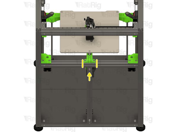
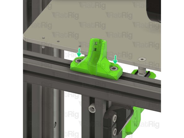
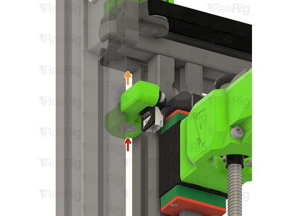
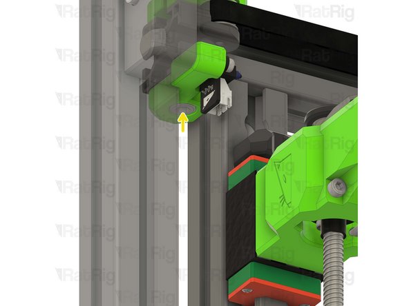
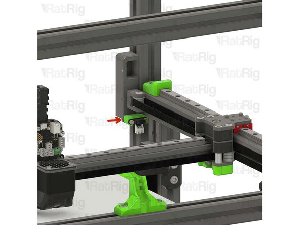
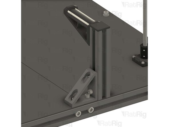
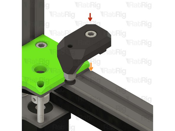
Y endstop mount assembly
-
Install the Y endstop mount assembly to the left side of the V-Core 4 frame as shown.
-
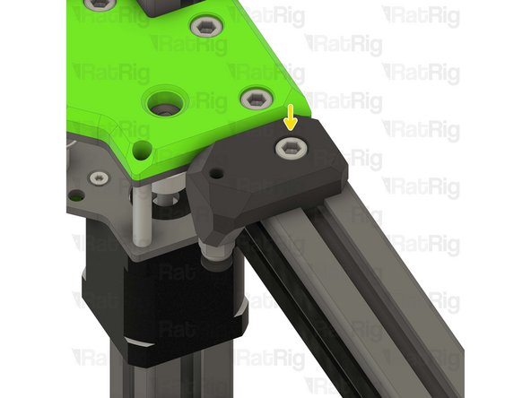
Tighten the M6x12 screw to secure the Y endstop mount.
-
Take care not to over-tighten the M6x12 screws as you can damage the printed parts
So on mine the gantry will hit the tensioner before it triggers the endstop? Is that a design issue or am i missing something? I'll built out the sensor with some washers but it feels like a weird oversight or, more likely, I messed up somewhere.
Yeah, probably you messed somewhere.... can't see where, but you did. Mine is perfect now.
-
-
-
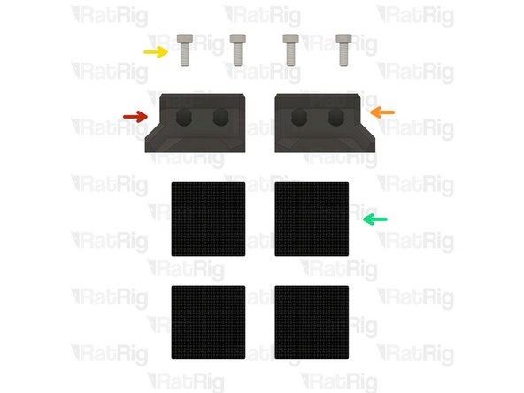
1x vc4_wiper_left
-
1x vc4_wiper_right
-
4x M3x8 Cap Head Screw
-
4x Felt Pad - 25x25x3mm
4x M3x8 Cap Head Screw >>>> SKU: HW1502SC
4x Felt Pad - 25x25x3mm >>>> SKU: HW3780GC
Vasco Rocha - Open Reply
No, they are standard. My kit is the Hybrid single toolhead and I got two wipers as well. Later I will buy the idex kit if I put this one to good working :)
-
-
-
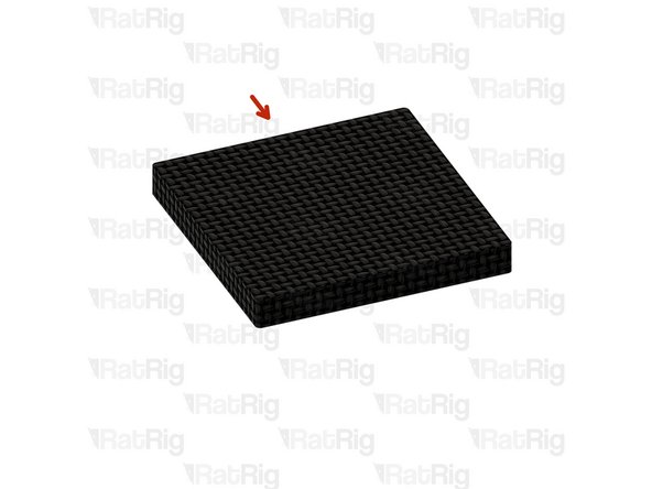
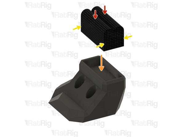
Felt Pad - 25x25x3mm
-
Peel the white paper on the back of the felt pads.
-
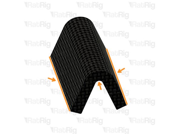
Bend all of the four felt pads as shown in order to insert them into the wiper housings.
-
Prepare four pads for the next step.
-
-
-
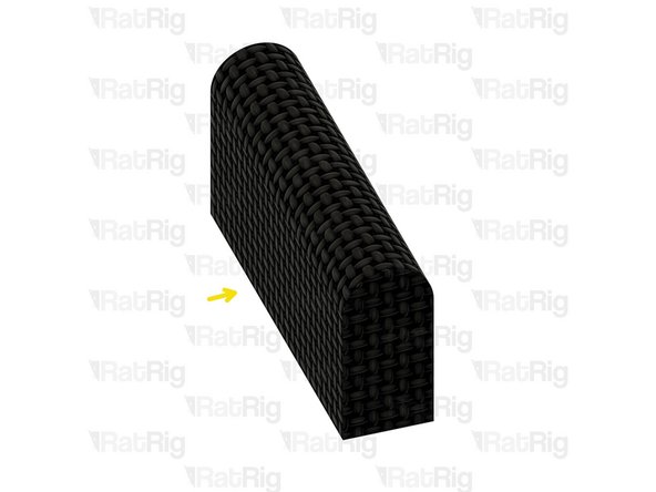
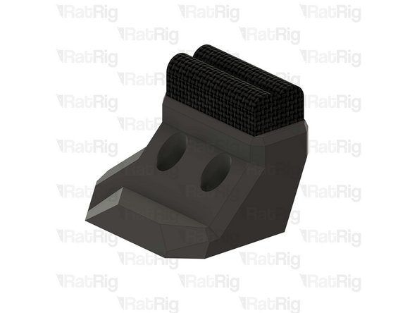
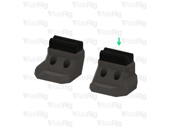
2x Felt Pad - 25x25x3mm
-
1x vc4_wiper_left
-
Squeeze two bent felt pads together while inserting them into the wiper body.
-
Repeat this step for the other wiper housing as well.
-
-
-
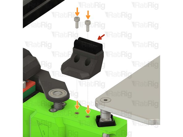
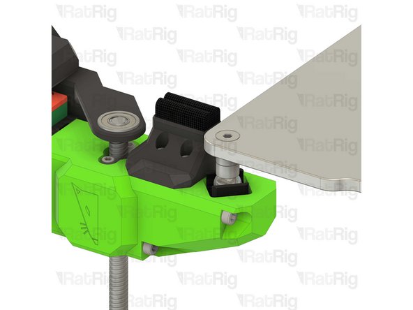
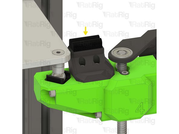
Left nozzle wiper
-
2x M3x8 Cap Head Screw
-
Secure the nozzle wiper to the bed arm as shown.
-
Take care not to over tighten the M3x8 screws as you can damage the printed parts.
-
Repeat this step to attach the opposite side nozzle wiper.
The parts are too low to be usefull, the toolhead will collide with the bed if used. They need to be about 3-5mm highter.
Some code that uses those things can be found in
RatOS-configuration/macros.cfg search for
_CLEANING_MOVE TOOLHEAD={0 if default_toolhead == 1 else 1}
-
-
-
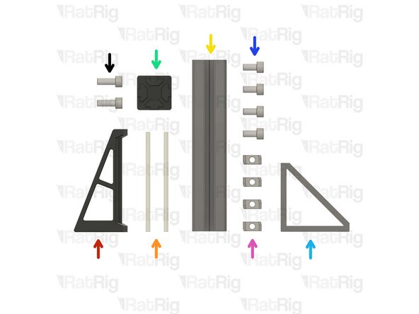
1x vc4_spoolholder_arm
-
2x 87mm PTFE Tube
-
1x T-Slot 3030 extrusion- 150mm
-
1x 3030_end_cap
-
1x Extruded 90° Corner- 6030 Tall
-
4x M6x12 Cap Head Screw
-
4x 3030 Drop-in T-Nut - M6
-
2x M6x16 Cap Head Screw
Is this an upgrade??? Why I didn't receive this on my package? Was it an option to be selected on the buying list? If it is... then I haven't seen it. will I have to make a spool holder myself or ask ratrig for this option???
Vasco Rocha - Open Reply
-
-
-
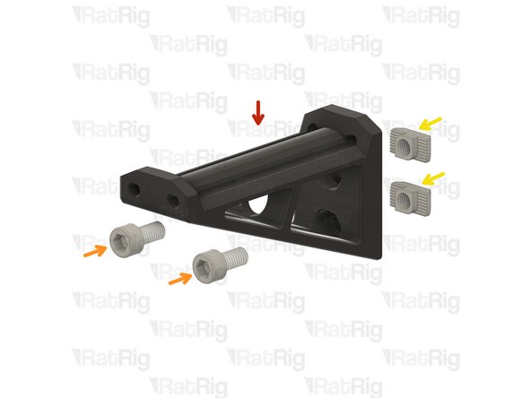
vc4_spoolholder_arm
-
2x M6x12 Cap Head Screw
-
2x 3030 Drop-in T-Nut - M6
-
Install the M6x12 Cap head screws into the spool holder as shown.
-
Loosely thread a 3030 T-Nuts onto the M6x12 screws. Do not tighten it at this point.
-
-
-
vc4_spoolholder_arm
-
87mm length of PTFE tubing
-
Using a sharp blade (such as a utility knife), cut two lengths of PTFE tubing measuring 87mm in length.
-
Insert a length of PTFE into each channel of the spool holder as shown.
Threading some M3 screws or grubs into the ends of the PTFE will hold it in place.
Kyle Blair - Open Reply
-
-
-
1x Extruded 90° Corner- 6030 Tall
-
2x M6x12 Cap Head Screw
-
2x 3030 Drop-in T-Nut - M6
-
Install the M6 cap head screws into the corner bracket as shown.
-
Loosely thread a 3030 T-Nuts onto the M6x12 screws. Do not tighten it at this point.
-
-
-
T-Slot 3030 extrusion- 150mm
-
Corner bracket assembly from the previous Step
-
Attach the corner bracket assembly to the aluminium extrusion, aligning the flat edges together.
-
3030_end_cap
-
Place the printed cap on the other end.
-
Tighten the M6x12 screws to secure the corner bracket to the extrusion.
-
Ensure the extrusion is flush with the corner bracket
-
-
-
Spool holder printed part
-
T-Slot 3030 extrusion- 150mm
-
Attach the spool holder printed part to the aluminium extrusion as shown, aligning the top edges.
-
Tighten the M6x12 screw to secure the spool holder to the extrusion.
-
Take care not to over tighten the screws as you can damage the printed parts.
-
-
-
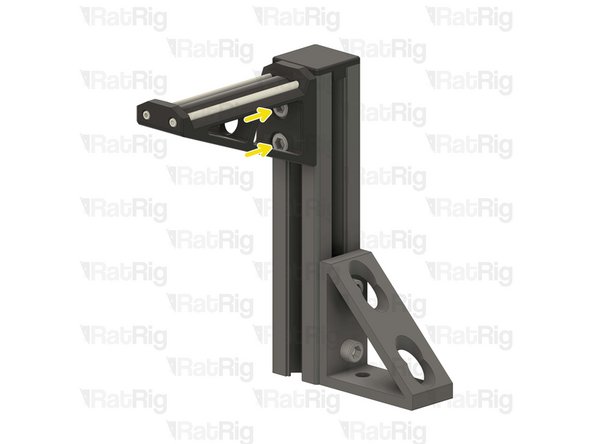
The spool holder can be mounted on either side of the machine, this guide will instruct you to install it on the left side of the machine for single-head configuration.
-
2x M6x12 Cap Head Screw
-
2x M6 Washer
-
Remove the shown M6x12 screws and their corresponding washers in order to allow for the spool holder arm to be installed.
-
Avoid moving the machine around or bumping into it, to prevent the t-nuts from moving.
-
-
-
Spool holder arm assembly from the previous Step
-
2x M6x12 Cap Head Screws removed from step 22
-
Align the corner bracket of the spool holder with the holes in the base plates.
-
Carefully tighten the M6x12 screws to the T-Nuts inside the base aluminum extrusion, securing the spool holder in place.
-
-
-
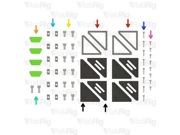
4x Extruded 90° Corner- 6030 Tall
-
4x vc4_trim_diffuser
-
12x M6x12 Cap Head Screw
-
2x M6x16 Cap Head Screw
-
12x 3030 Drop-in T-Nut - M6
-
8x M3x16 Cap Head Screw
-
8x M3x8 Cap Head Screw
-
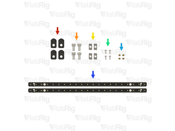
4x vc4_trim_front + 4x vc4_trim_rear
-
-
-
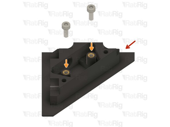
vc4_trim_rear
-
2x M3x8 Cap Head Screw
-
These screws will be used to hold an Led PCB module, coming soon
-
Prepare the four assemblies.
I think there needs to be a step for heat set insertsforbtue other 2 holes. Cannot screw into anything on step 30.
There is no need for heat inserts there. The holes are meant to pass through screws to tighten into the heat inserts on the other part.
On my parts there seems to be a sacrificial layer in the way that needs to be removed.
Mathis -
-
-
-
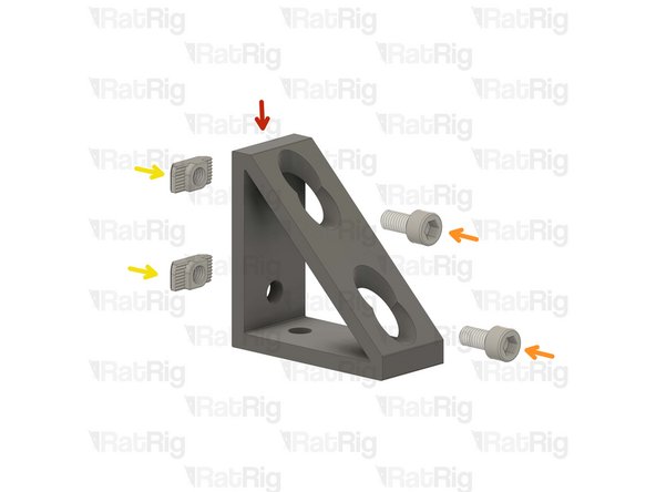
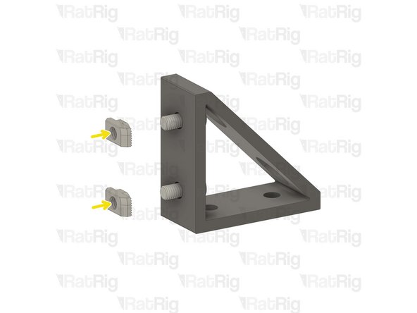
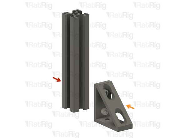
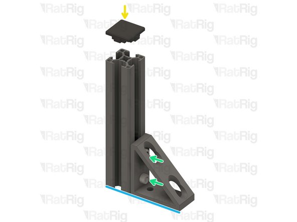
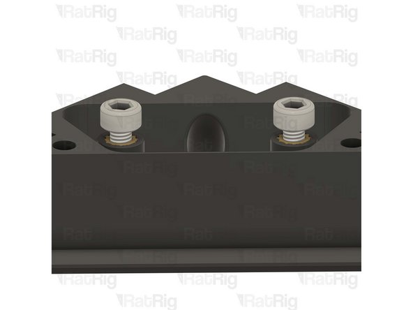
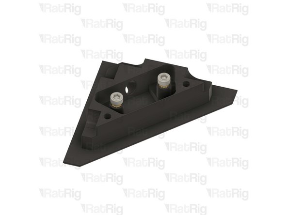
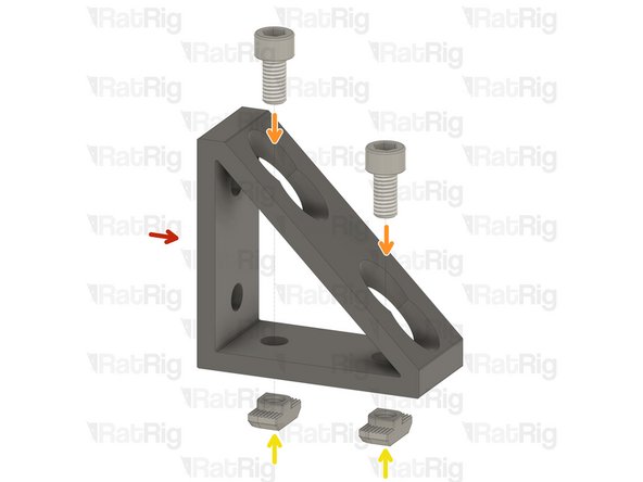
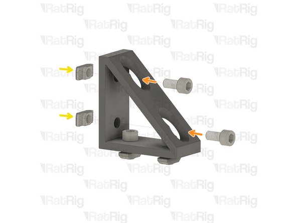
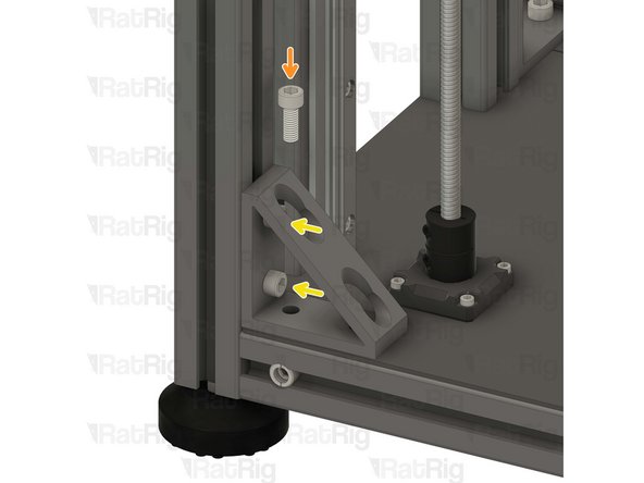
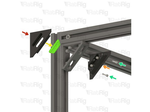
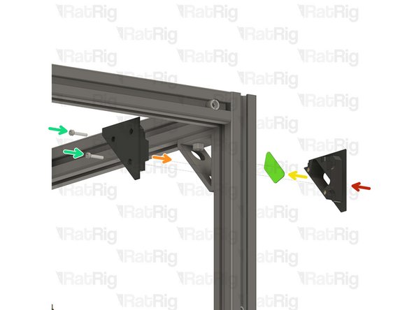
Extruded 90° Corner- 6030 Tall
-
4x M6x12 Cap Head Screw
-
4x 3030 Drop-in T-Nut - M6
-
Install the M6 cap head screws into the corner bracket as shown.
-
Loosely thread a 3030 T-Nuts onto the M6x12 screws. Do not tighten it at this point.
-
Repeat this step one more time, then go back and follow through Step 19 twice with the remaining corner brackets.
-
-
-
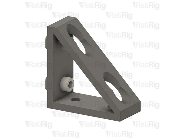
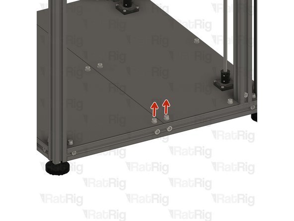
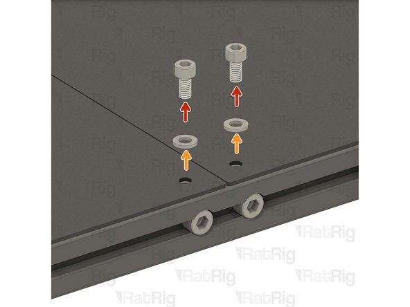
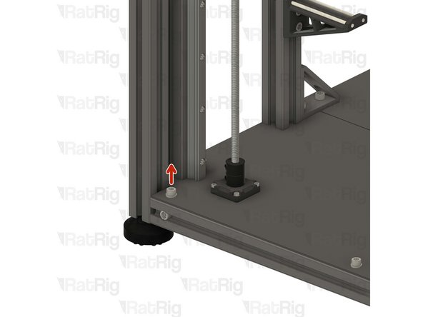
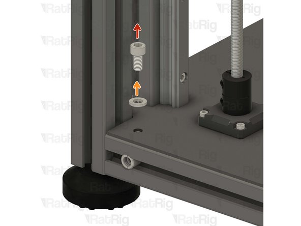
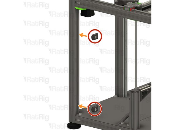
1x M6x12 Cap Head Screw
-
1x M6 Washer
-
Remove the highlighted M6x12 screw and the corresponding washer in order to allow for the lower corner bracket assembly to be installed.
There are two M6x12 with washers here on recent machines and 2 M6x16s to replace them.
Steve O'Hara-Smith - Resolved on Release Reply
-
-
-
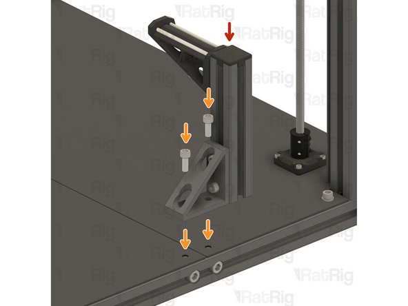
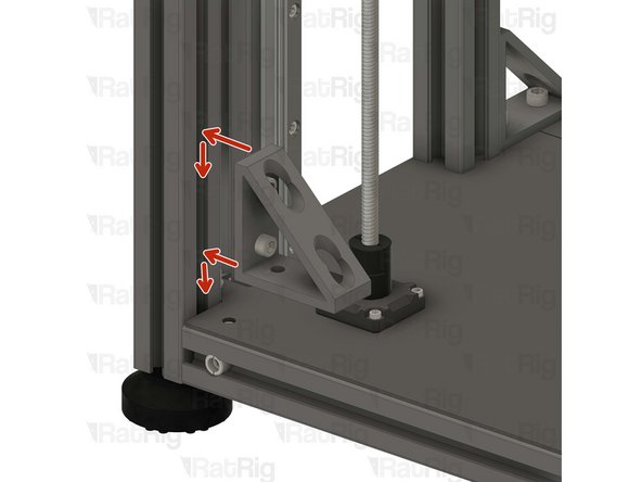
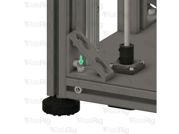
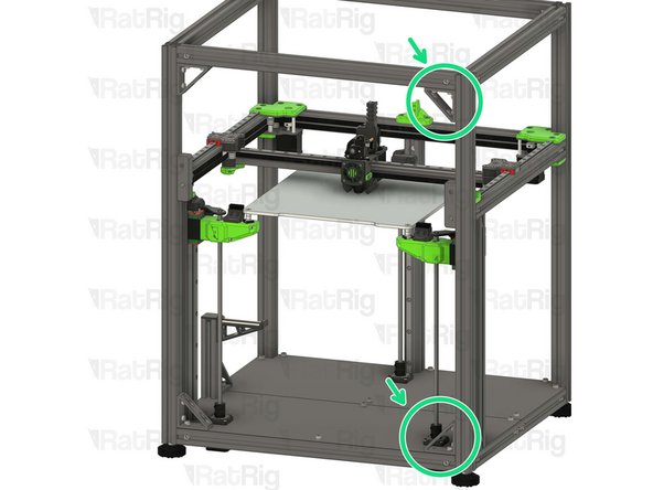
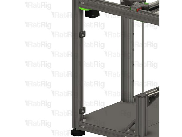
Lower corner bracket assembly
-
1x M6x16 Cap Head Screw
-
Install the lower corner bracket to the V-Core 4 frame as shown.
-
Tighten the M6x12 screws to attach the bracket.
-
Carefully tighten the M6x16 screw to the T-Nut inside the base aluminium extrusion, securing the bracket in place.
Similar to step 23 (spool arm), the M6x16 is too long. I reused the M6x12 without the washer to screw the lower corner bracket assembly into the base.
The 16 isn't too long. If the T nut fails to rotate into place it will seem like it is though.
-
-
-
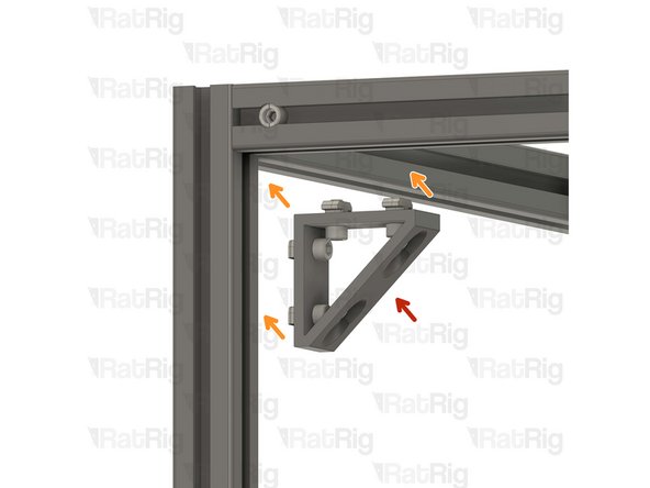
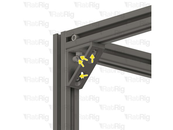
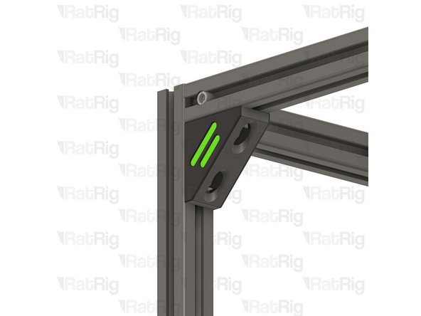
Upper corner bracket assembly
-
Install the upper corner bracket to the V-Core 4 frame as shown.
-
Tighten the M6x12 screws to secure the bracket to the frame.
-
Repeat Steps 27, 28 and 29 to attach the rest of the brackets to the other side.
-
-
-
1x vc4_trim_front
-
1x vc4_trim_rear
-
1x vc4_trim_diffuser
-
2x M3x16 Cap Head Screw
-
Tighten the M3x16 screws into the front trim printed part, inserting them through the rear trim printed part.
-
Sandwich the parts together enclosing the diffuser inside the corner bracket.
-
Take care not to over tighten the screws as you can damage the printed parts.
At this step if like me some printed part don't fit in it, check the print, mine where horrible quality, I had prints with misaligned layers, so I had to cut the shape myself to make it fit on 3 out of 4 pieces... I would have really preferred not to have to buy the printed parts as before... And have them printed for the same price somewhere where they would have been of much better quality.
I guess one of my metal corners was narrower than the other three as I had to remove about 2mm off the thickness of the trim prints in order for them to tighten on the corners. The centers were making contact and still the trim was very loose on the metal corner even with the 3x16 screws fully tight.
A quick solution I found to keep the trim diffuser in place was to bunch up a piece of a paper towel and stuff it in there. You can also back out the two m3x8 screws a little bit to apply some extra pressure to the paper towel.
Maksymilian Pizzochero - Resolved on Release Reply
-
-
-
1x vc4_ptfe_guide_upper
-
1x Bowden Pass-through Adaptor
-
1x M6x12 Cap Head Screw
-
1x 3030 Drop-in T-Nut - M6
vc4_ptfe_guide_upper is in the same bag as the spool holder parts.
Diomedes Dominguez - Resolved on Release Reply
-
-
-
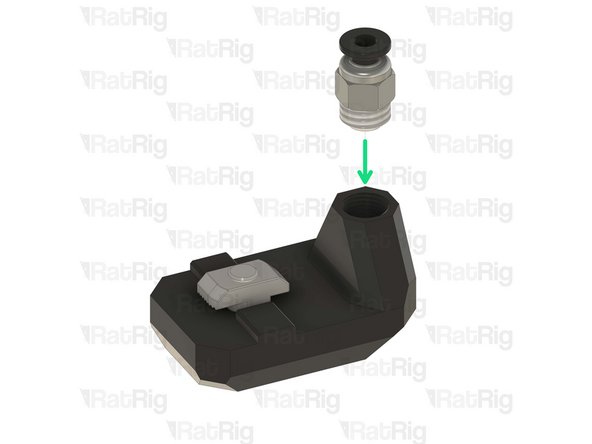
vc4_ptfe_guide_upper
-
1x M6x12 Cap Head Screw
-
Install the screw into the PTFE guide as shown.
-
1x 3030 Drop-in T-Nut - M6
-
Loosely thread a 3030 T-Nut onto the M6x12 screw. Do not tighten it at this point.
-
Bowden Pass-through Adaptor
-
Thread the bowden adapter into the printed part and secure it in place.
-
Take care not to over tighten the bowden adapter as you can damage the printed parts.
I have to agree with marc, I printed this with High quality ASA on an H2D at work, 0.4 nozzle, 0.2 layer height, high quality, slow speeds, part came out perfect in 1 shot. Started threads by hand, finished with a wrench. I decided to self-source for all the printed parts, and im glad I did, all the parts that did come with my kit are only just serviceable and only just in spec, not what I could consider the highest of quality.
Clearly the printers used are
1) not calibrated correctly
2) not set at the right precision for this part where threads are involved.
I reprinted on an x1c with 0.1mm layer height. All other settings as recommended. It threaded perfectly, first half smoothly by hand and the rest with my 10mm. Perfect fit, not too tight or loose. No need to scale up or down the print here, the STL is perfect as is, all printer settings. I would appreciate RagRig fixing this, yes I have a printer and was able to get past this but the point is I paid for this and it's not usable. Part of my product cost, shipping cost and duties even if minimal on one part went towards something unusable. This is also far from the only part out of spec, another one needing a reprint was the toolhead toolboards, their off-spec caused bad alignment with the hex standoff. I could go on and on.
It's worth beating this dead horse. I reprinted these using ASA and they fit perfectly the first attempt. Mind you, I used a .1mm layer height. This part never should have shipped.
Kyle Blair - Open Reply
My choice was a little tricky. I took a 9.0 mm drill with very low speed. After that a 9.5 mm drill and then it works.
(@RatRig)My suggestion would be, make a 10 mm hole and use a little superglue.
At the end the part was broken. I made a better part with a nut. Download at "https://www.thingiverse.com/thing:696318....
Erik -
The problem is the threaded area of the print needs to be printed at .1mm layer height. On my prints (IDEX) both had many of the threads not even connected to the print. Just loose strands of plastic not adhered to anything. That's because at .2mm layers or larger they have nothing to connect to on the previous layer.
Or if Ratrig made the walls thicker, they could just print the hole to slightly over the ID of the thread and then the user could self tap the bowden pass through connector. This would not require the fine layer height.
This part needs work. The part I received was printed with such tight tolerances that merely screwing the PTFE adapter in a couple threads caused it to delaminate and fall apart. The tolerances should be looser, and the walls around the adapter should be thicker to handle the stress.
Brigandier - Resolved on Release Reply
Same experience as Mathis here. Way to much printed part need rework, I'm loosing at least an hour or two at this stage...
FoG Ryu -
Exactly the same. Print quality of the parts is so attrocious that it was the exception for any of them to work out of the box.
Had to do plenty of drilling, milling and filing to at least make it functional.
Mathis -
Had a similar issue. Managed to get the part assembled (twice for the IDEX kit), but I had to go incredibly slow and gentle. It took a lot of trial and error to get the fitting to thread in straight and I don't think I have it seated all the way in the hole, but I stopped short when it got extra difficult to continue.
This one has been the worst, but this feels like a common theme with the printed parts in this kit - they have all felt rushed and not well printed/inspected. Overhangs and surface finish have been mediocre to bad, and several parts have been warped or not fit correctly.
Hunter -
I had the exact same issue, no way i could safely get it on, even tried to drill a size under so it would self thread the rest, but there was too little mass around the hole.
-
-
-
Upper PTFE guide assembly
-
Install the PTFE guide assembly to the left back side of the V-Core 4 frame as shown.
-
Tighten the M6x12 screw to secure the upper PTFE guide.
-
Insert the PTFE tubing through the bowden clamp, as shown. Then connect it to the orbiter extruder.
-
Take care not to over tighten the screws as you can damage the printed parts.
Agree. Even with trimming, the clamp fits like garbage. I'm printing new ones with modifications.
Kyle Blair - Open Reply
I'm wondering if RR is sending out a slightly different diameter of PTFE tubing now. I had to drill out the hole in the guide to accommodate the tube.
I also was unable to fit the provided PTFE tube section into the toolhead plate back in section 8 (or 9 for IDEX). I had to use a skinnier PTFE tube I happened to have on hand from another printer.
-
-
-
2x vc4_ptfe_guide_lower
-
2x M6x12 Cap Head Screw
-
2x 3030 Drop-in T-Nut - M6
-
-
-
vc4_ptfe_guide_lower
-
1x M6x12 Cap Head Screw
-
Install the M6 cap head screw into the PTFE guide as shown.
-
1x 3030 Drop-in T-Nut - M6
-
Loosely thread a 3030 T-Nut onto the M6x12 screws. Do not tighten it at this point
-
Repeat this step one more time to assemble the other PTFE guide.
-
-
-
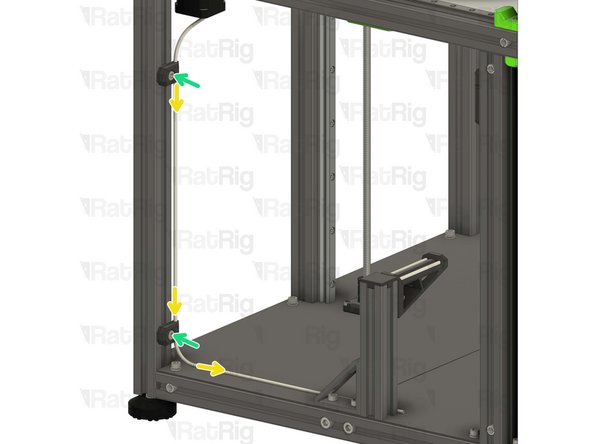
2x Lower PTFE guide assembly from the previous Step
-
Position the PTFE guide assemblies on the left side of the V-Core 4 frame.
-
Insert the PTFE tubing into the guides, as shown.
-
Tighten the M6x12 screw to secure the guide assemblies and PTFE to the frame.
-
Take care not to over tighten the screws as you can damage the printed parts.
-
-
-
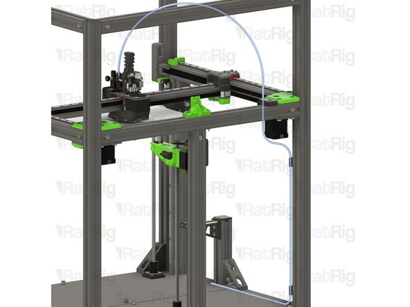
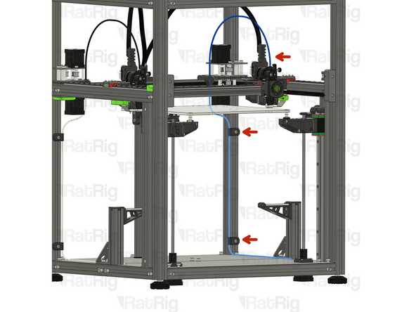
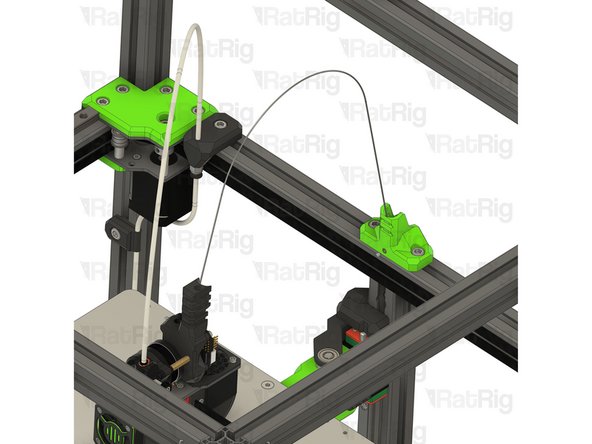
It is recommended to route the PTFE filament guide as shown.
-
If you are assembling the IDEX, go back to Step 32 and complete an additional filament path assembly, on the opposite side of the machine.
Why not put the filament at the top of the frame vs this super long path???
Largely because a typical cabinet height is 30 inches, plus the 38 inches of height of the 500, would put the filiment somewhere around 6 feet in the ait, above what many can reach.
Steve -
would be nice to have a printed part to attach PTFE tube to spool holder
Michele Ciacci - Resolved on Release Reply
-
-
-
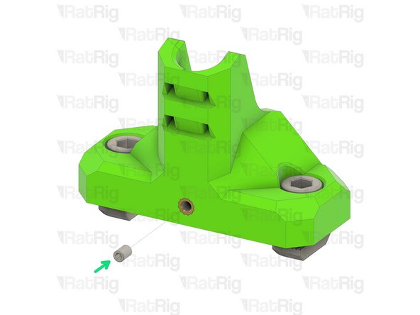
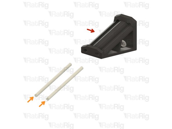
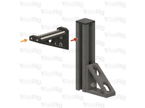
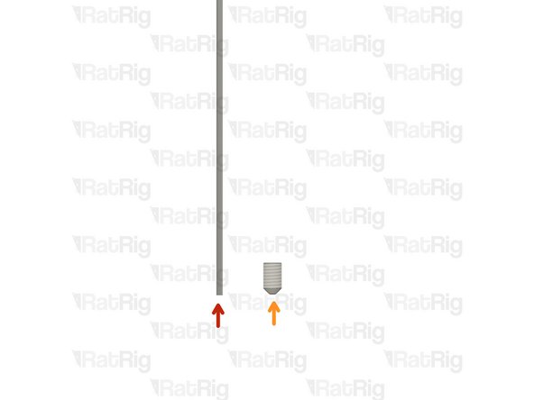
Piano Wire for Umbilical - 1000mm x 1.00mm
-
M3x5 Set Screw
-
The Piano wire need to be cut to length for you machine:
-
V-Core 4 300 - 650mm
-
V-Core 4 400 - 750mm
-
V-Core 4 500 - 850mm
-
Use a strong set of cutting pliers, as the piano wire is super stiff and can break small pliers.
never assume that you will receive 1 meter of the piano wire, so measure the whole length of it twice, just to ensure the correct position to cut according to your machine. Also, you can give 3 to 5 mm beyond the specified length, it's better that than buying another wire.
Diomedes Dominguez - Resolved on Release Reply
-
-
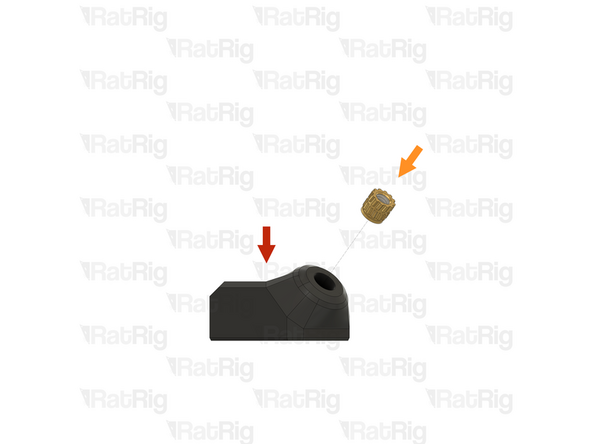
-
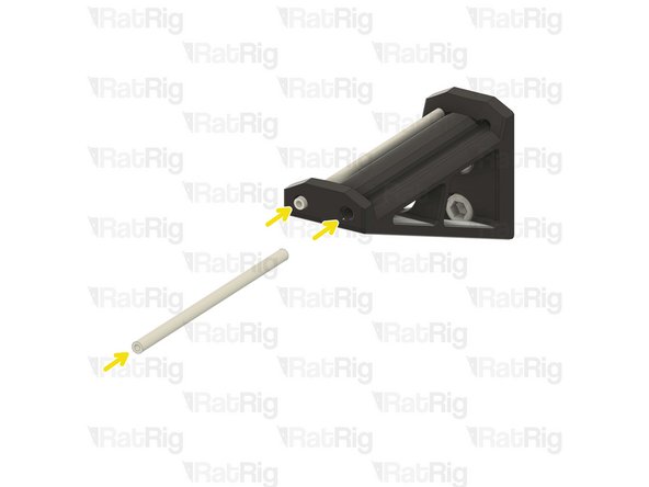
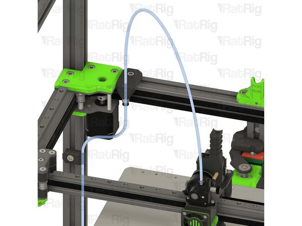
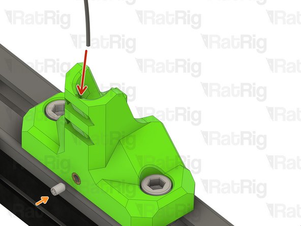
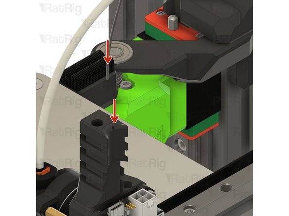
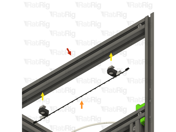
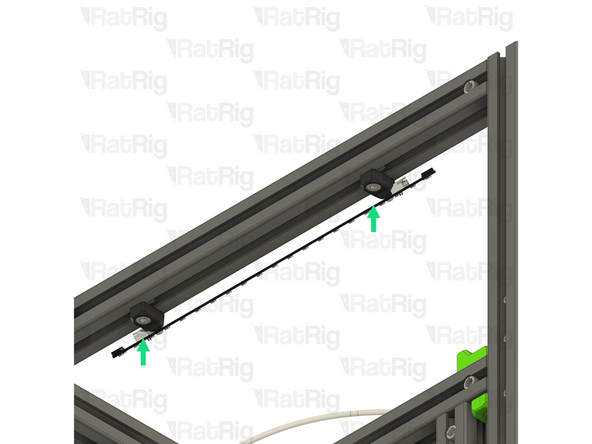
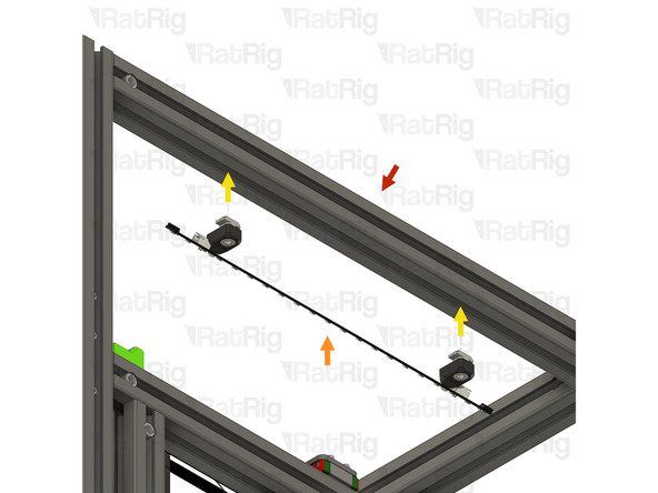
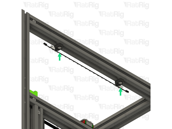
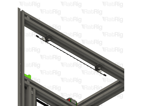
Insert the piano wire into the designated hole in the vc4_umbilical_frame printed part
-
thread the M3x5 set screw to secure the Piano wire in place
-
-
-
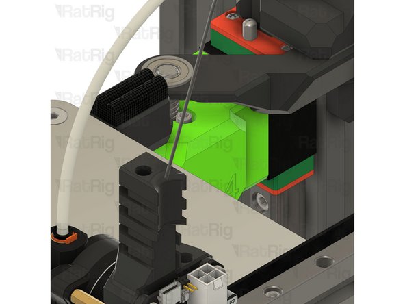
Insert the other end of the piano wire in the designated hole on the EBB toolboard mount
-
Be careful, the piano wire is super stiff, do not allow it to swing freely as it can hit you and create injury.
-
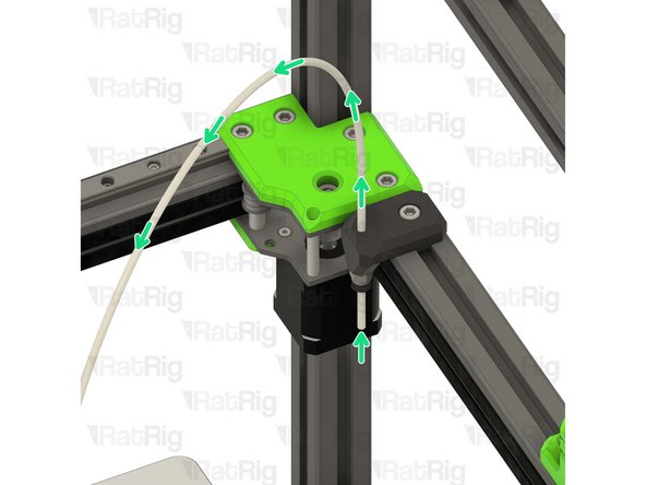
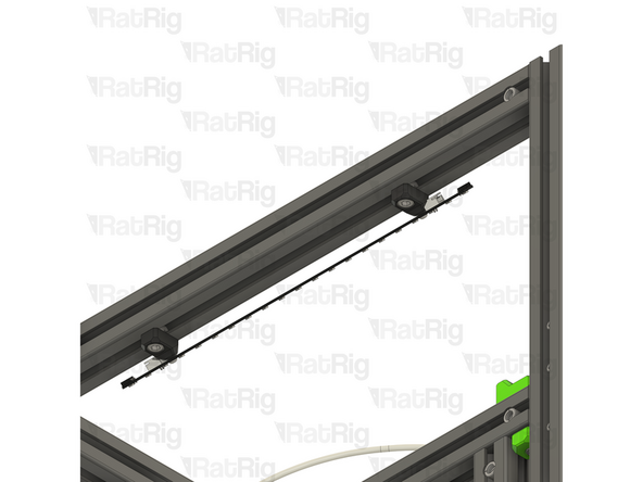
Once installed it should look like the picture, the piano wire will provide support to the USB and power cables, improving Input shaper results
Lesson Learned: Don't heat piano wire to melt plastic while inserting into tool head. Overheating will make it more brittle and break. Broke off 20mm of wire in tool head.
Easiest way to install is using a drill. The hole is not straight, do not recommend a drill bit if you have the size. Instead use the wire as a "drill bit". Insert one end into drill chuck and sand the far end to a point (like preparing tungsten for TIG welding). Insert pointy end into tool head hole and "drill" in ~35mm. Feed the wire with hand into toolhead, shouldn't have to apply much force, the wire will dig the hole.
I don't know if umbilical height is going to be an issue with a top enclosure panel, but my gut tells me yes. I'm ordering additional 3030 extrusions to build a riser. Additionally, I will install some cross bars with lights for better chamber illumination.
3030 extrusions are available from McMaster Carr. Black anodized to match. Along with all of the joining solutions you can imagine. It appears an additional ~200mm of height would be required to clear the umbilicals.
Kyle Blair - Open Reply
I gotta say, I was really pleased with the quality of everything until these last couple steps. The umbilical frame insert should probably be an M4. The M3 came right out with virtually zero pressure. I melted it back in with a ton of CA glue.
Kyle Blair - Open Reply
I cut my piano wires to the required 650mm length for a 300mm machine, and I notice that when the Y axis is moved all the way to the rear the wire loop extends quite a bit above the top of the frame. Is that going to be a problem later with an enclosure top?
Denver Hull - Resolved on Release Reply
I checked the CAD for IDEX before doing mine. IDEX uses the same umbilical mount (and only the one). It was pretty hard to get both wires in, but managed it with pliers. The bottom of the channel is only a layer or two, so shoved until both wires poked out and then shoved them back into the part slightly. Then tightened the set screw. FAR easier to do with the mount removed from the chassis.
How deep is the hole in the toolboard mount for the piano wire? Mine didn't seem to go in more than 6mm or so.
Yeah that isnt happening for me. All 3 toolhead mounts barely took 3mm and I had to drill the holes to get it to even 6mm. 35 just isnt happening on mine!
Matt -
If you take a look at the CAD Files you can see that it's about 35mm. 6mm is not enough at all.
Hergen -
-
-
-
4x vc4_led_holder_frame printed part
-
4x M6x12 Cap Head Screw
-
4x 3030 Drop-in T-Nut - M6
-
4x M3x8 Button Head Screw
-
4x M3 heat insert
-
2x Rat Rig Dayspring LED strip - 310mm
Is this an upgrade? I didn't receive this. My kit was ordered on July/August 2024 and I didn't see any option on this.
Vasco Rocha - Open Reply
-
-
-
1x vc4_led_holder_frame
-
1x M3 heat insert
-
Install a heat insert into the printed part as shown
-
Prepare four of these parts
-
-
-
LED frame mount from the previous step
-
1x M6x12 Cap Head Screw
-
Insert an M6 cap head screw into the printed part as shown
-
1x 3030 Drop-in T-Nut - M6
-
Loosely thread a 3030 T-Nut onto the M6x12 screws. Do not tighten it at this point
-
Prepare four of these parts
-
-
-
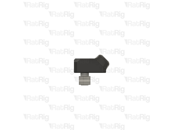
1x Rat Rig Dayspring LED strip - 310mm
-
2x LED frame mount from the previous step
-
Align a frame mount assembly with mounting hole on the LED strip
-
2x M3x8 Button Head Screw
-
Insert an M3x8 button head screw through the mounting hole in the LED strip and screw it into the printed mount
-
Assemble two LED strips
-
-
-
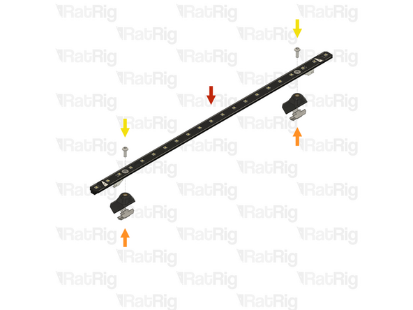
Rat Rig V-Core 4.0 assembly - Left side
-
1x LED strip assembly from the previous step
-
Align the LED strip mounts with the frame, making sure both T-nuts slot into the extrusion slots
-
Secure the LED strip to the frame by tightening both M6x12 screws
-
Take care not to overtighten the screws as you can damage the printed parts
-
-
-
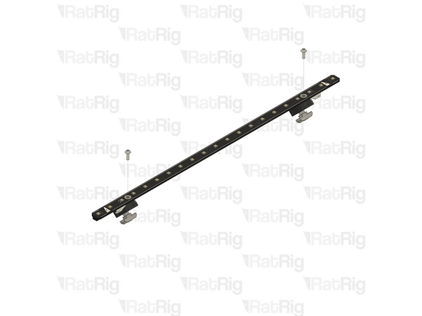
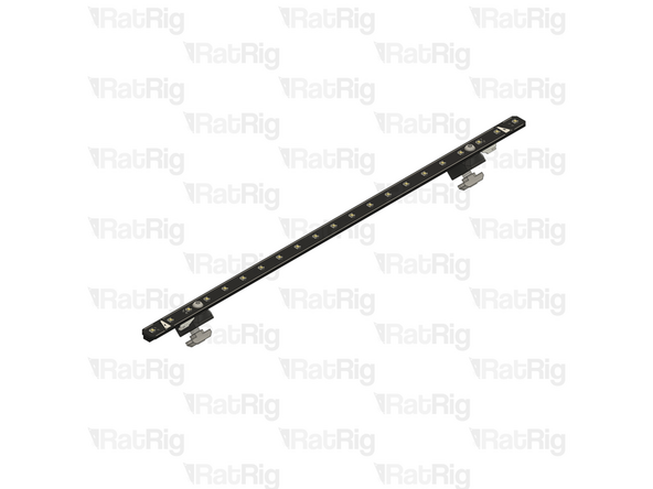
Rat Rig V-Core 4.0 assembly - Right side
-
1x LED strip assembly from the step 45
-
Align the LED strip mounts with the frame, making sure both T-nuts slot into the extrusion slots
-
Secure the LED strip to the frame by tightening both M6x12 screws
-
Take care not to overtighten the screws as you can damage the printed parts
-


Cancel: I did not complete this guide.
34 other people completed this guide.

One Comment
Im IDEX mode due i Not need a second Piano wire for the other printhead? There is only one wire
ds3975@gmail.com - Open Reply
I'd assumed these were ABS and just about melted off the first insert. Much better luck running iron at ~225
Ag_Back - Resolved on Release Reply
According to ratrig the parts are printed in ABS. I typically use a lower temperature (compared to print temp) when installing heat sets as it's easier to control how they go in.
Bill -
Really wish you guys kept the green :(.
Adam F - Resolved on Release Reply
I've brought the printed parts from Rat Rig, but the heat inserts are not in place.
Kai - Resolved on Release Reply
On July's video they inform that they wouldn't continue selling the printed parts with pre-mounted inserts.
Diomedes Dominguez -