
-
-
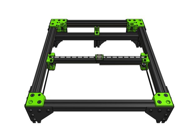
The focus of this guide is the X gantry which requires 2 printed parts which you can identify with the letters on the back:
-
R for right (looking from the front of the printer)
-
L for left
-
Take note of the difference between the shim types:
-
Micro
-
Mini
-
Spacer
-
-
-
You will use the micro shims only on the top and bottom of the toothed idlers. All other shims are the mini shims.
-
The toothed idlers are on the front and the smooth idlers are on the back of the XY Joiners.
-
The left XY Joiner has its toothed idler on top of the stack and the smooth one in the bottom.
-
It's the other way around for the right XY joiner - toothed idler in the bottom and the smooth one on top of the stack.
-
The tolerances on the XY Joiner parts are minimal and that's by design.
I write this here up front, for everyone that wants to try the build like I did.
I did not follow the order described, as I read the warnings about the difficult belt inserts at the end.
Instead I first connected the gantry and the printed left and right parts. Then I screwed the metal plates onto the rails and placed the gantry on top. Then I started to insert the idler stacks by using a hex allen key from below the part through the adapter plate. This way I could add the belt while stacking the parts and it was totally easy to do so.
You might consider the help of another person to stack though, as the stacking while holding the allen key at the same time gets somewhat acrobatic at times :D Good part placement is key.
After the stacking and screwing the m5x55 through I attached the finished gantry to the metal adapter plates. This way the belts were already routed correctly.
(PS: To move the gantry for the rail alignment you can easily pull on both the loose belt ends on the side you want the gantry to go)
Material List is:
4 micro shims
8 Mini shims
8 Spacers 6mm
2 toothed Idlers
2 smooth Idlers
4 cap head screws M5 x 55
Flip Breukers - Resolved on Release Reply
-
-
-
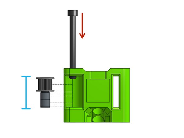
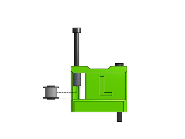
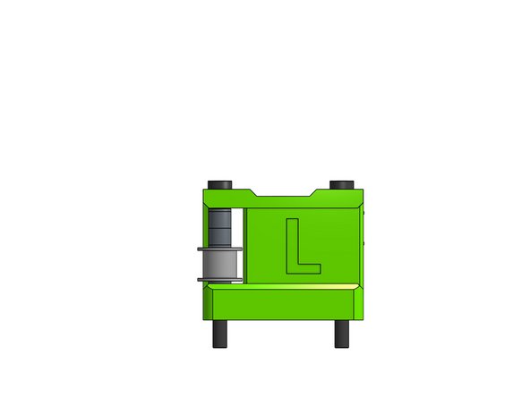
Insert the left toothed stack on the Cap Head Screw M5 x 55
-
Step by step insert the screw while adding the stack parts onto it: micro shim, toothed idler, micro shim, 2x 6mm spacers, mini shim
Just a tip so you don’t do what I did, go ahead and put and m5 nut on the end so you don’t have to worry about them falling out when you do the next step.
Mike James - Resolved on Release Reply
-
-
-
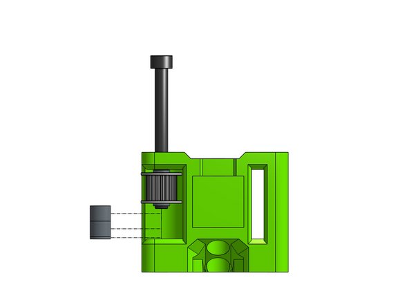
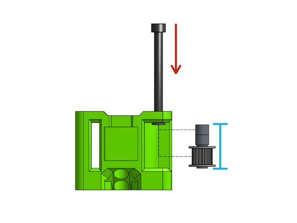
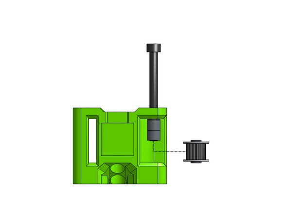
Insert the left smooth stack on the Cap Head Screw M5 x 55
-
Step by step insert the screw while adding the stack parts onto it: mini shim, 2x 6mm spacers, mini shim, smooth idler, mini shim
I over tightened the cap head screws. The idlers did not want to spin freely. I backed the screws off a quarter turn and then they spun freely. You might want to double check all your idlers before you get to adding the belts.
Paul Largent - Resolved on Release Reply
-
-
-
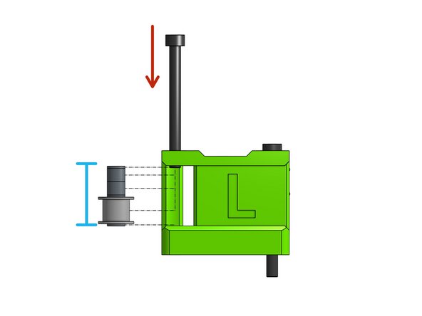
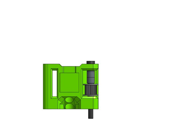
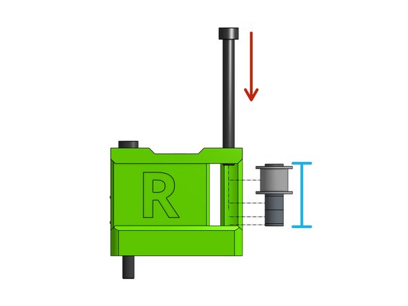
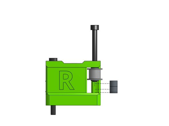
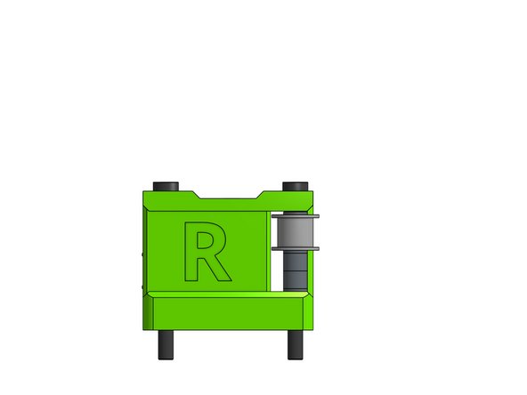
Insert the right toothed stack on the Cap Head Screw M5 x 55
-
Step by step insert the screw while adding the stack parts onto it: mini shim, 2x 6mm spacers, micro shim, toothed idler, micro shim
-
-
-
Insert the right smooth stack on the Cap Head Screw M5 x 55
-
Step by step insert the screw while adding the stack parts onto it: mini shim, smooth idler, mini shim, 2x 6mm spacers, mini shim
-
-
-
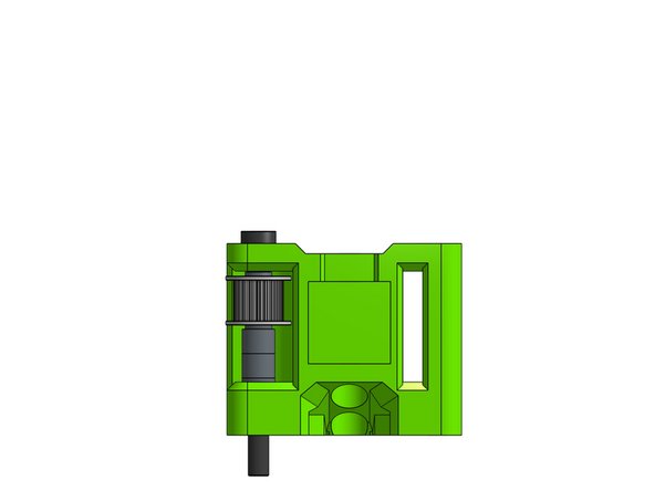
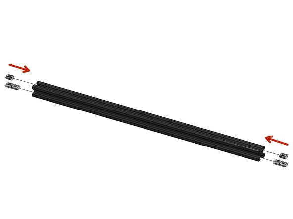
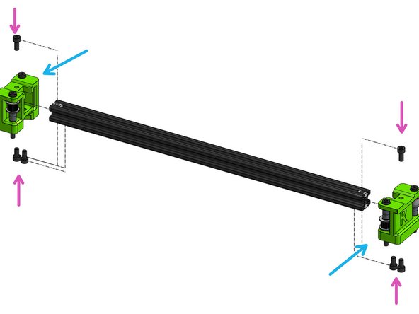
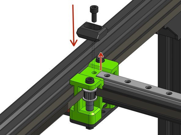
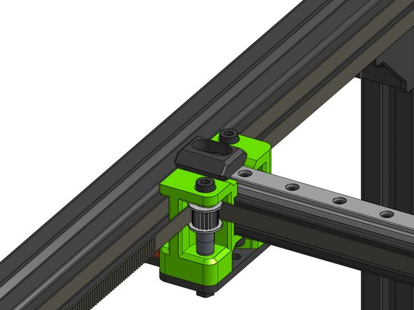
Slide the square nuts into the 2020 extrusion: 4 in the bottom slot and 2 in the top.
-
Slide the XY joiners on the 2020 exrusion
-
Watch out not to pinch your fingers!
-
Fasten everything together with 4x Cap Head Screws M5x10 from the bottom and 2x Cap Head Screws M5 12 from the top, those bolts need to firmly grab the square nuts that are in the profile
You should call the square nuts “square slide in T-nuts”. There are actual square nuts in the packaging that are used in other places. This would let you be more specific and direct the builder to the correct part with less confusion.
Paul Largent - Resolved on Release Reply
To make the insertion of the 2020 into the plastic Joiners easier, I beveled the sharp edges at the end of the 2020 with a small needle file.
Jeff Jones - Resolved on Release Reply
What are the exact dimensions of the 20x20 extrusion for a 500x500 machine?
FWIW, I’m looking to replace this part with a CF tube.
422 on a 300, 522 on a 400 and 622mm on a 500. This can be checked at https://v-core.ratrig.com/bom/
Rat Rig -
-
-
-
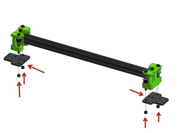
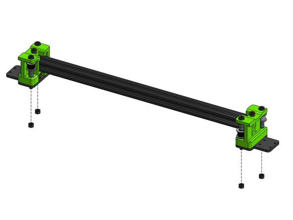
Slide the two XY plates on the M5 screws and bolt them down with M5 nuts
-
Do not over tighten or you will be compressing the bearings.
The plates where not parellel so the rail did not align and did not drive smooth.
I drilled the 4 holes in both plates of 3mm with a 4 mm drill: aligned and smooth like sunshine!
Sander Luiten - Resolved on Release Reply
In addition to Elco Jacob’s comment I would like to add that even if your printed parts are perfectly square and a snug fit to the 2020 extrusion and other parts, there can still be a problem with skewed plates that mount on the rail carriages. I don’t like solutions that are irriversable (such as sanding something down) without understanding what the actual cause is. So I looked closer into the problem. My parts were square and as good as you can expect from a printed part. Yet, when I tightened the bolts that hold the printed part to the extrusion, the plates skewed with their outer tips down by 0.15mm to 0.2mm left/right. What I did was test which one of the bolts could be fastened without the plate skewing. This were the top bolts. I then shimmed the space at the bottom bolts so it could no longer skew when tightened. This fix is actually closer to the real issue in my case, and is reversable and adjustable. Hope that helps!
If there is a gap, sanding the surface to make it flat will help. Loosen the screws from the previous step that hold the printed part to the extrusion. Press down so the plates make full contact with the flat surface. Then carefully put the assembly on its side and tighten the screws again. Finally, put the M5 nuts back on.
Elco Jacobs - Resolved on Release Reply
I think a crucial step that should be added to the guide is to ensure that the extrusion and the plates are perfectly parallel. If your printed parts have a small ridge (elephants foot from printing), it can cause misalignment. The result will be that your linear rails will start binding when you tighten the screws that hold the plates to the rails. The rails can slide very smoothly until you fully tighten.
To check and properly align: remove the 4 M5 nuts at the bottom of the plate. With the screws inside but loose, put the assembly on a flat surface and press down lightly. Check that there are no gaps between the plates and the surface or the plates and the printed part. If there is a gap, sanding the surface to make it flat will help.
Elco Jacobs - Resolved on Release Reply
obvious from remaining parts… but should call these m5 nuts out as m5 nylon nuts
Daniel Moran - Resolved on Release Reply
-
-
-
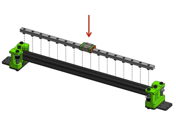
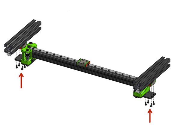
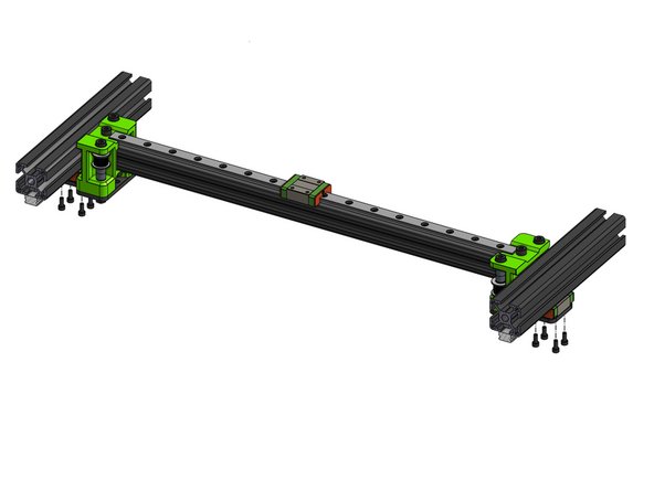
Attach the prepared MGN rail to the 2020 extrusion
-
Before Make sure to fasten all cap head screws
-
Please refer to the linear rail installation guide for instructions on the correct order to fasten the cap head screws
-
-
-
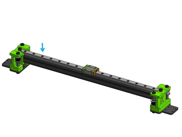
You may need to loosen the Y MGN rails for the rail to fit
-
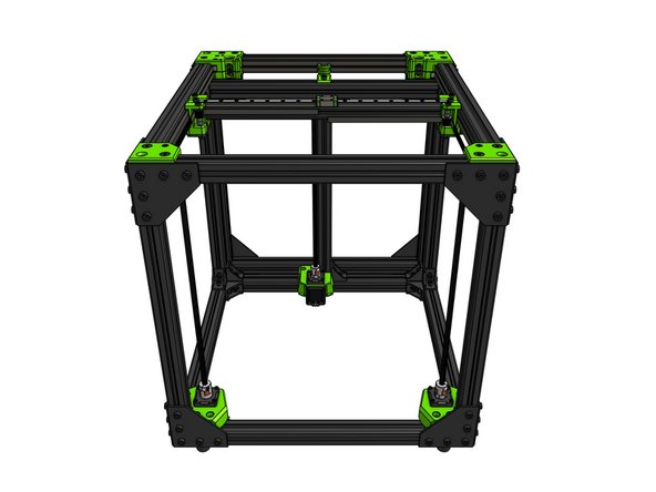
Attach the X gantry to the frame with 8x Cap Head Screws M3x8. Do not tighten those fully yet.
I found putting the xrail in and getting square easy with the printer upside down. Also makes putting the belts in a lot easier as you can lift the sides and thread the belt as required, gravity is working for you. It does need raising slightly for this to work as the x carriage connectors hit the deck.
Raise it up or it feels like it’s binding. I read the the above and forgot the last part. I have no idea how much time I spent trying to figure out why it bound up when it was just hitting the table.
Warning, missing step!
There are no instructions for installing the X rail to the 2020 extrusion.
Do we have to remove the endstops from the X rail before installing it on the 2020 extrusion?
Eduard Baniceru - Resolved on Release Reply
-
-
-
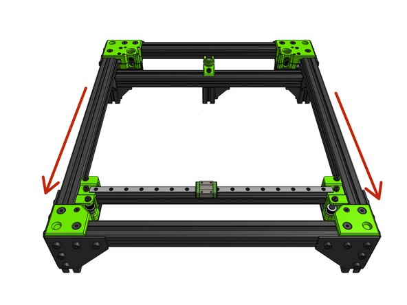
This step assumed you left the Y MGN rails screws loose
-
Please refer to the linear rail installation guide for instructions on the correct order to fasten the cap head screws in the following steps
-
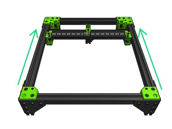
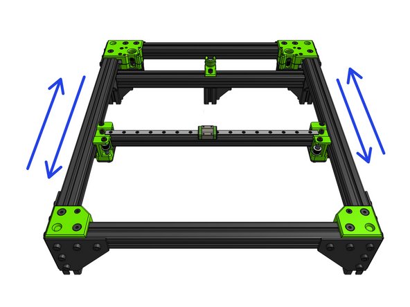
Move the X gantry to the front of the frame and back to uncover the first hole in the rail
-
Fully fasten in the first Y MGN screws locking their position in the X dimension of the printer while at Ymin
-
Move the gantry to the back and fully fasten the last screws of the Y MGN rails locking the rails position in the "X of the printer" at Ymax
-
Lock the 8x screws holding the X gantry to it's MGN carriages
-
Move the X gantry back and forward a few times to ensure there are no spots where the gantry moves less freely. If the gantry gets caught somewhere loosen the MGN rails and repeat the process
-
Fully fasten all of the Y MGN screws and check again if the gantry is not binding
Georg makes an excellent comment. I would only add that the best way I found to be sure the m5 screws were as loose as possible yet still tight enough, was to loosen the m5 screws until you can twist the plastic part (about x) and just barely be able to move it off the steel plate. Then slightly tighten until you can no longer make any gap between the steel and the printed part. This will prevent any unwanted movement when printing, but keep the parts loose enough so they doesn’t cause too much noise in the y axis and reduce bearing wear.
Thanks for the top Georg. I ended up doing a lot of sanding as it seemed like I had printed the plastic parts at an angle (which is likely as the printer I used was not high quality). But ultimately, I succeeded in making the parts flat, so when mounted on the metal holders they didn’t force the rail carriages to in rest crookedly on the Y-rails.
Jakob Ventzel - Resolved on Release Reply
Problem: with the M3 screws from the gantry plates to the rails being loose, the gantry moves very smoothly. But when you tighten them, it makes unpleasent noises. Then do the following:
1. Untighten the M5 screws a little (printed parts to gantry plates), not only should the idlers move very easily, but it also influences the rails. If tightened only a little too hard, the wagon on the rail is tilted and doesnt move freely anymore.
2. If not enough: remove the gantry from the printer and the plates from the gantry. Place the plastic parts (with the M5 screws pushed in, be careful not to let them fall out) on a flat surface. If it wobbles on the surface or has a gap between the surface and the printed parts, do the following: Put a piece of sandpaper on the surface and move the printed part on it, so the underside is sanded and gets flatter. Keep the other printed part on the surface so everything is flat and repeat on the other side. This improved things for me. Although still not as good as with loose screws.
-
-
-
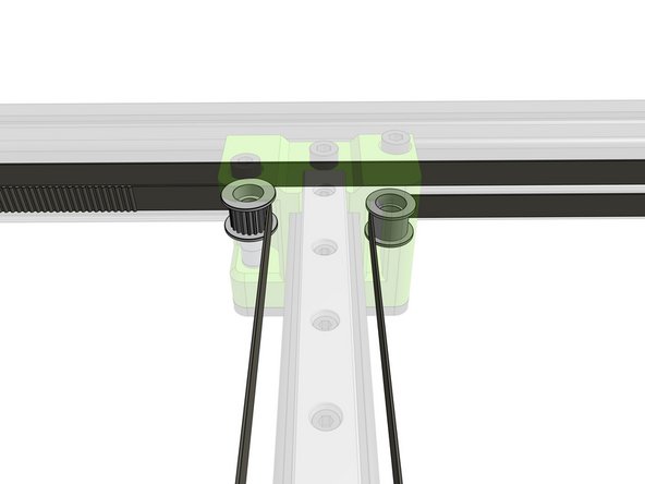
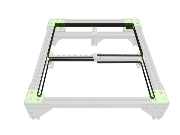
Fold the belts through the XY joiners so that all 4 ends end up in the middle of the X gantry.
-
Don't try to cut the belts to length yet!
In addition to the above comments I found that it was extremely easy to tie a thin piece of string to any small piece you can feed through the rear slot and then tie the other end of the string to your belt and simply pull it all though like mule tape. The zip ties I had lying around were too short to easily do this process by themselves but with some string it easily fed through the first time.
Even easier than feeding a zip tie through, is to feed the other belt through the difficult side so the teeth mesh with the difficult belt. Then pull the other belt back through, and the difficult belt will be pull along with it.
joshua43214 - Resolved on Release Reply
I can be difficult to feed the belt from the rear in through the slot, I found that if you feed a thin cable tie (zip tie /kable binde) from the opposite direction the belt will follow the curve of the cable tie.
morphelan@gmail.com - Resolved on Release Reply
-
-
-
Loosen the Cap Head Screw M5x12 and fasten it back through the X endstop block part
I also struggled a bit here. The X-Endstop part is rather flimsy, and I followed Murray’s suggestion to put a shim underneath to support the end stop as to bot break it apart when tightening the M5 bolt. Like many others I also needed to use a 14mm long M5 as the 12mm provided couldn’t reach the square nut in the extrusion.
Jakob Ventzel - Resolved on Release Reply
Other stated that it should be an M5x14 but I was able to used the default m5x12 with the 3d printed parts from rat rig themselves without any modifications. With that said YMMV
Absolute Prodigy - Resolved on Release Reply
I had an extra 6mm shim washer left over which I put between the endstop block and the left XY joiner to fill the gap and not break through the bottom of the stop as the bolt was retightened. I sanded the stop so that it fit and slide easily off the end of the rail (there is a right way and a wrong way to put the stop block on, its bottom groove has to align with the rail).
Murray McEwan - Resolved on Release Reply
I’m a bit disappointed with the endstop arrangement, The adjustment part on the EVA can’t be adjusted once it’s assembled (I’m using a BMG extruder option), so not sure why it’s made adjustable. The switch is held in place by screws that screw into the plastic arm and I overtightened one so I then needed to add a nut on the other end. It would be a better to go with nuts from the start I think. Then the switch lever contacts only the very outer corner of the block which also has the problem others have described as a very thin plastic base. I redesigned my block to eliminate these last two issues as I felt the end stop will become unstable over time if I left as it was.
As Daniel noted, be careful screwing this piece down as it is very thin. On top of that, check for a lip between the XY joiner and the linear rail. In my case, the joiner was too short. I didn’t notice until screwing down the piece and it cracked under almost no force. The linear rail stuck up above the joiner by about 2mm. That lip combined with the very thin piece almost guaranteed that the endstop wasn’t ever going to be secured very well.
Anthony McDevitt - Resolved on Release Reply
Agree with Tom’s comment, this really should be a m5 x 14. However, I was able to use the 12mm by tipping the printer on its side, causing the square nut to come closer to the rail.
Mike James - Resolved on Release Reply
It’s roughly clear this is the left side of the gantry… but should be pointed out in the docs. Should also point out not to tighten this down to tight. The plastic holding this endstop is really thin where it bolts down and i cracked mine… and yup, an M5x14 was nice upgrade here Tom. Forgot to mention the picture at the top of this page does not show the end stop. Nor does the picture at the bottom or subsequent steps.
Daniel Moran - Resolved on Release Reply
-
-
-
This guide does not include the assembly of an EVA carriage - your chosen EVA variant can be assembled last
EVA is a modular carriage platform for MGN style linear rails used on 3D printers. The main goal is to support a wide variety of hot ends and extruders in common use on a variety of 3D printers including the Rat Rig V-Core-3. You can find all the EVA details, printable parts and guides at the EVA web site https://main.eva-3d.page/ The build guide for EVA on a Rat Rig V-Core 3 with Bondtech BMG extruder and E3D V6 hot end is included in section 8 of this build guide.
Paul Largent - Resolved on Release Reply
-


Cancel: I did not complete this guide.
38 other people completed this guide.

2 Comments
Hello,
One change to this manual that I would suggest is mounting the X-Rail only after installation in the Frame and leave all screws somewhat loose until all is installed in the frame and the paralellity is checked. If one of the endcaps is only 1 mm to one side the installation is no longer possible which makes loosening all screws on the rail nescessary.
The flatness of XY joiners aren't good , mines come wrapped, after mount on the plate and on rails ,twisted the gantry and the linear bearings don't slide well, I had to mill them.
Amsha - Resolved on Release Reply
My plastic “XY joiners” required some post processing. There was plastic drooping down from where unsupported bridges were printed. They touched the idlers and prevented them from spinning. A shot from my heat gun/lighter/torch and a little pressure smoothed the errant fibers and pushed them back into the main plastic part. A little bit of sanding or filing would produce the same result.
Paul Largent - Resolved on Release Reply
So looks like i used micros on the first set of idlers, does this mean i have to redo them all for this step or can i just use minis
James Andros - Resolved on Release Reply
The two toothed idlers have a bearing with smaller OD so you may get some rubbing if you use the larger shims..
cairn -
Is anyone else having problems getting the ends to fit on the 2020 extrusion. Both of mine were too tight to fit in, it could be my printer, but I had to edit the STL s and make the 2020 hole 20.4 mm on each side.
david wilson - Resolved on Release Reply
My 3D prints that I made were not good on this step. The 2020 extrusion would not fit, and I’m reprinting. Good idea to check before you enjoy the fun of putting the idlers together only to realize you will have to do it again.
david wilson - Resolved on Release Reply
no micro shims in my kit
David Westendorf - Resolved on Release Reply
the difference between the micro and mini shim should be explained before doing idlers steps.
David Morgado - Resolved on Release Reply
I fully agree. luckily i picked the correct shim bag in the beginning. I noticed just in this step, that there is another bag with shims.
Martin Ro -