-
-
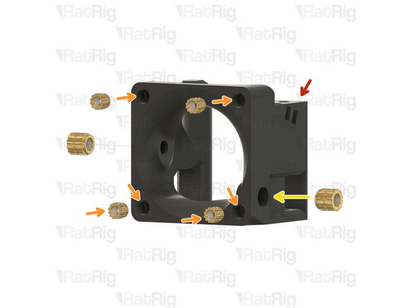
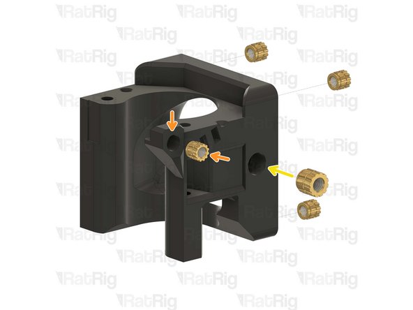
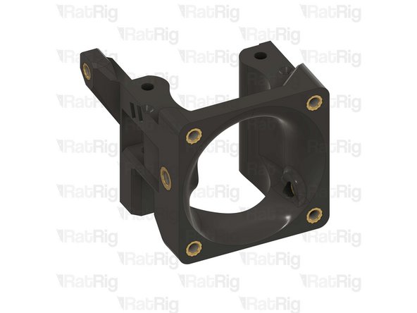
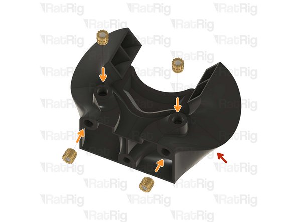
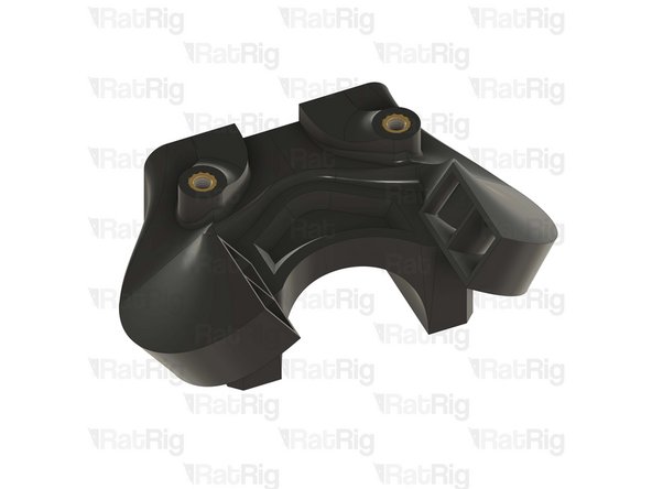
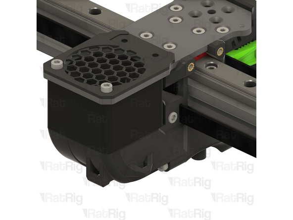
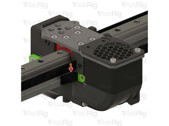
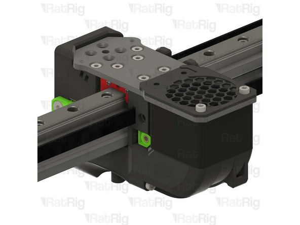
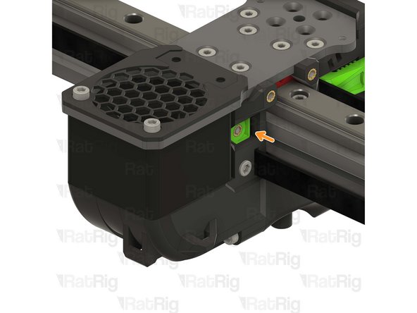
25x Heat Insert M3
-
2x Heat Insert M4
-
1x rr_vc4_toolhead_duct
-
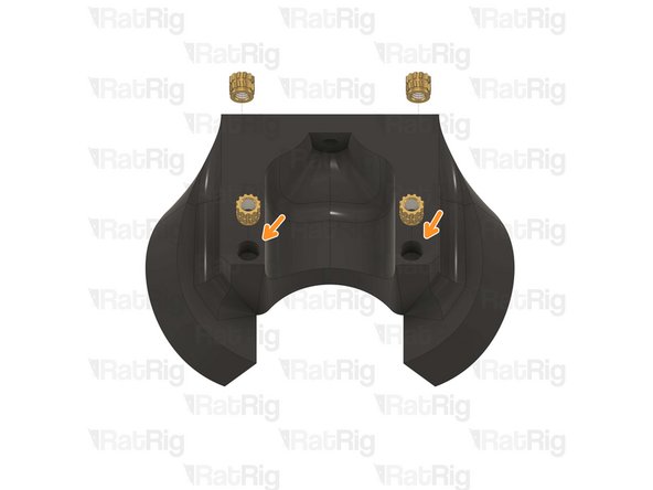
2x rr_vc4_toolhead_back_clamp
-
1x rr_vc4_toolhead_front
-
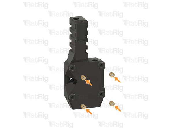
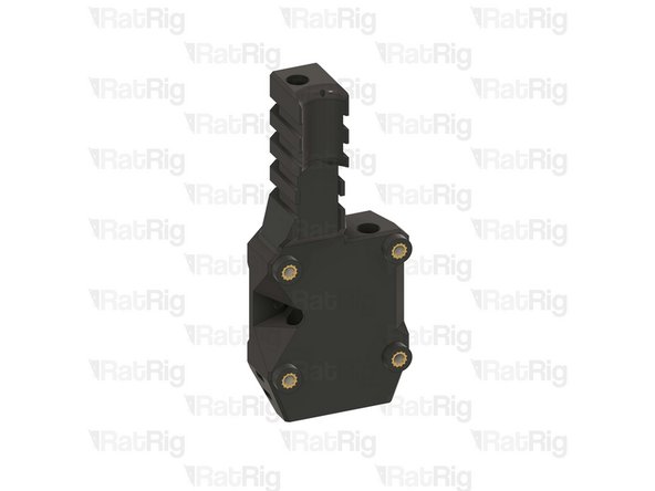
1x rr_vc4_toolhead_toolboard_vertical
-
1x rr_vc4_toolhead_back
-
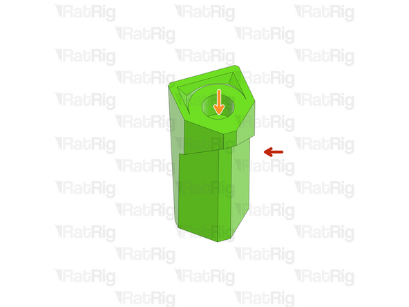
Clean the sacrificial layers on the rr_vc4_toolhead_back_clamp parts, obtaining a clean passthrough hole.
-
-
-
1x rr_vc4_toolhead_toolboard_vertical
-
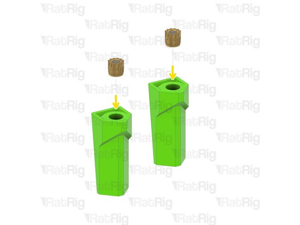
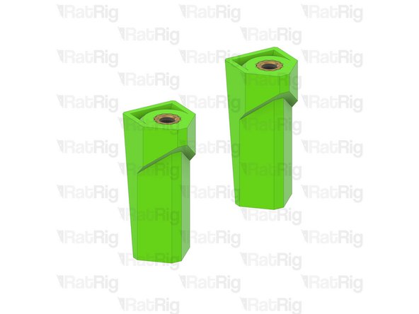
4x Heat Insert M3
-
-
-
2x rr_vc4_toolhead_back_clamp
-
Remove the sacrificial layer
-
2x Heat Insert M3
-
-
-
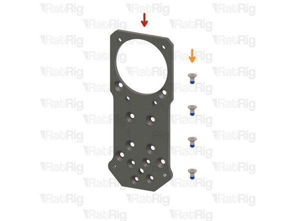
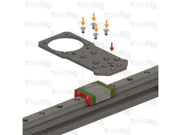
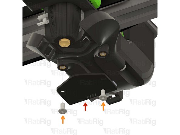
1x Rat Rig toolhead plate
-
4x M3x6 Countersink Screw with applied thread locker
-
-
-
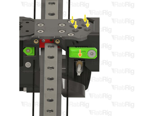
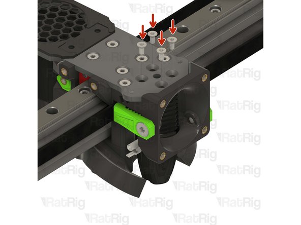
Rat Rig toolhead plate
-
4x M3x6 Countersink Screw
-
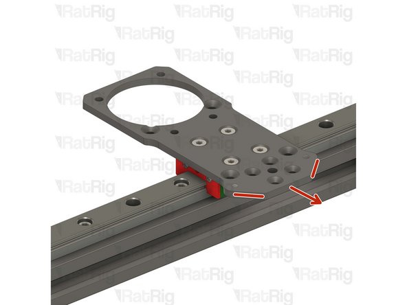
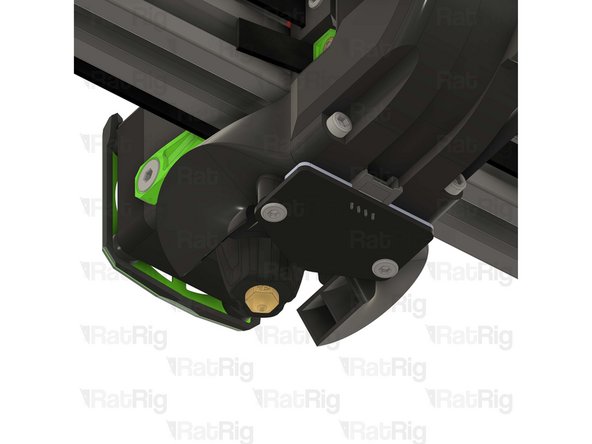
Tighten the M3x6 Countersink Screws to secure the plate to the carriage.
-
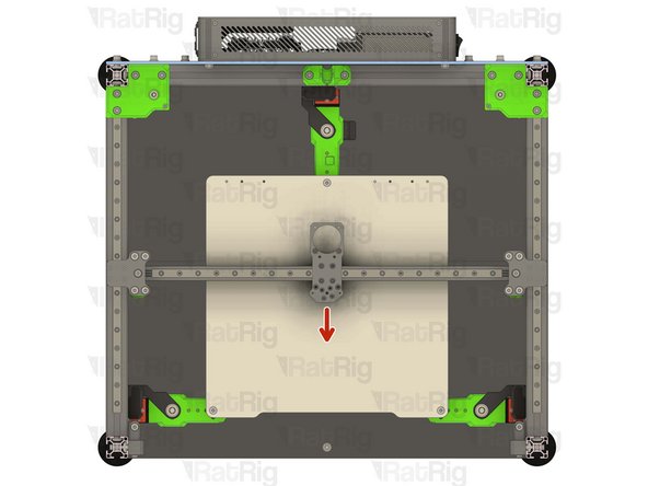
Pay attention to the orientation of the metal plate, having the pointy side towards the front of the printer, chamfered holes up.
-
Avoid using a ball end hex key, as they are more prone to damaging the sensitive M3 countersink screw head.
-
After tightening the screws, it is essential to verify that the X carriage retains its free movement. Excessive tightening of the screws may lead to the binding of the carriage.
-
-
-
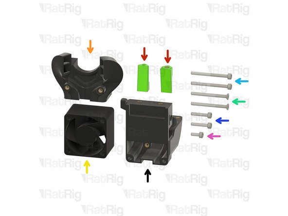
1x rr_vc4_toolhead_back
-
2x rr_vc4_toolhead_back_clamp
-
1x rr_vc4_toolhead_duct
-
1x 4028 Part Cooling Fan
-
2x M3x35 Countersink Screw
-
2x M3x35 Cap Head Screw
-
2x M3x16 Cap Head Screw
-
1x M3x8 Cap Head Screw
-
-
-
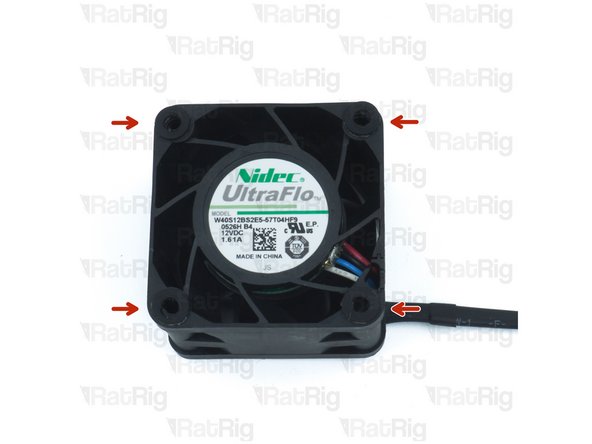
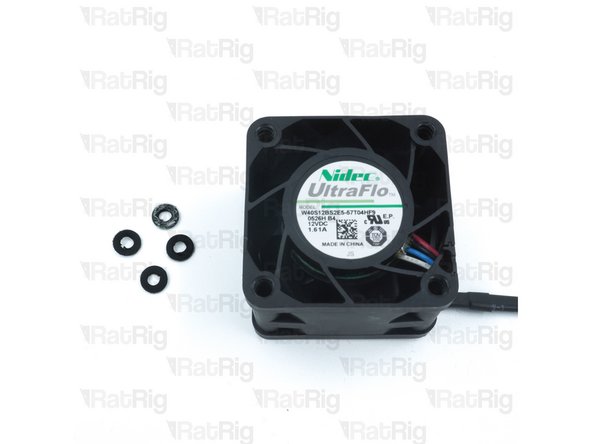
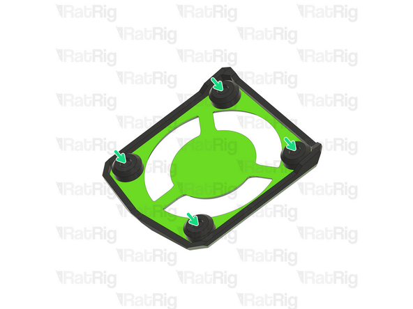
Remove the four rubber spacers on the 4028 Part Cooling Fan
-
-
-
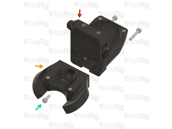
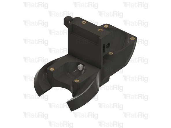
Rat Rig toolhead back printed part
-
Rat Rig toolhead duct printed part
-
2x M3x16 Cap Head Screw
-
1x M3x8 Cap Head Screw
-
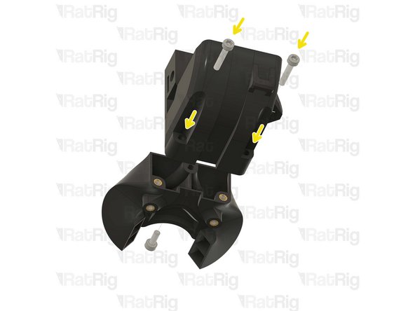
Insert the M3x16 screws through the back part and tighten them into the duct.
-
Feed the M3x8 screw from the opposite side and secure the parts together.
-
Take care not to over tighten the screws as you can damage the printed parts.
Consider mounting the Beacon probe here. If you do it later, you'll have to do it upside down while crawling under your toolhead.
See steps 35, 36 to decide:
-
-
-
Back part & duct sub-assembly
-
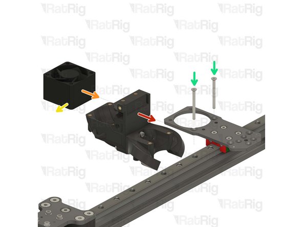
4028 Part Cooling Fan
-
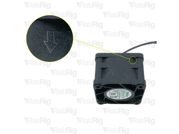
Pay special attention to the fan airflow, it should blow the air towards the cooling duct. Most fans have a small arrow indicating the airflow.
-
Point the fan wires to this side.
-
2x M3x35 Countersink Screw
-
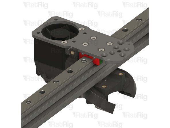
Feed the M3x35 screws into the toolhead plate, through the 4028 part cooling fan and tighten them into the printed sub-assembly.
-
Take care not to over tighten the M3x35 screws as you can damage the printed parts
-
Avoid using a ball end hex key, as they are more prone to damaging the sensitive M3 countersink screw head.
Before mounting the fan go to chapter 12. Electronics ***Step 64*** Prepare the 4028 cable parts
this is far more easier now to change the fan plug than after.
I would recommend cutting the 4028 fan cables at this stage and terminating it to the Molex Micro-Fit connector. It was quite tricky to recrimp the connector later on with the toolhead fully assembled.
Thanks for your comment ;)
Would be good to show also the orientation of the fan cables
-
-
-
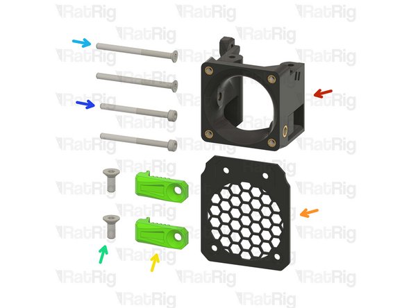
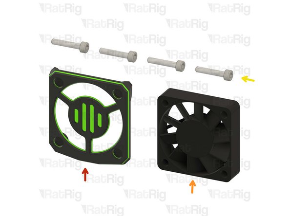
1x rr_vc4_toolhead_front
-
1x rr_vc4_toolhead_fan_grille
-
2x rr_vc4_toolhead_front_clamp
-
2x M4x10 Countersink Screw
-
2x M3x40 Countersink Screw
-
2x M3x35 Cap Head Screw
A suggestion for a resolution for these toolhead front clamps that are constantly failing.
Delete the M4x16 Countersunk Screws
Delete the countersink in the belt clamp
Drill the normal hole and use a Flanged Button Head Socket Cap Screws
This removes the countersink's already inherent weak spot and more than doubles the clamping force with the same torque applied!
-
-
-
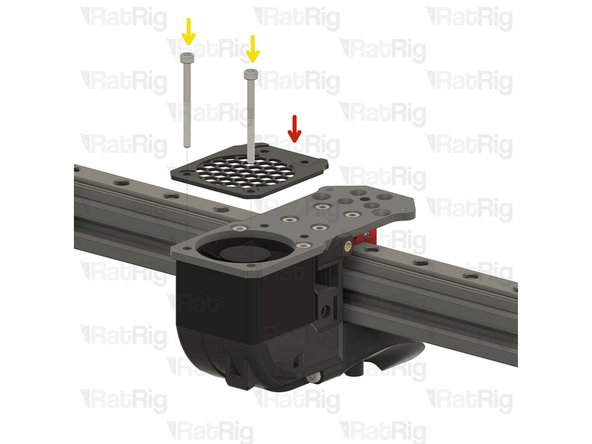
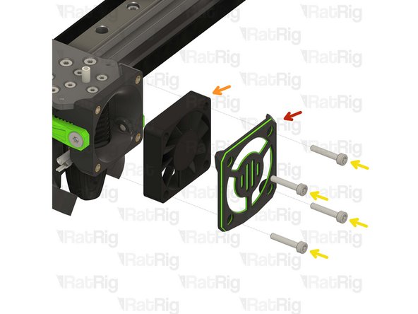
Rat Rig toolhead fan grille printed part
-
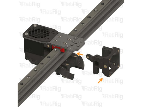
Rat Rig toolhead front printed part
-
2x M3x35 Cap Head Screw
-
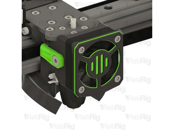
Feed the M3x35 cap head screws through the grille (pay close attention to its orientation), the aluminium plate and the 4028 fan, tightening them into the back printed part.
-
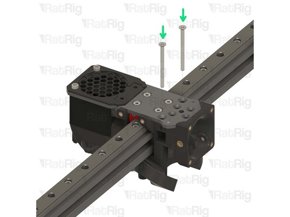
2x M3x40 Countersink Screw
-
The M3x40 countersink screws must go through the holes on the front assembly and thread into the duct assembly.
-
Take care not to over tighten the screws as you can damage the printed parts
-
Avoid using a ball end hex key, as they are more prone to damaging the sensitive M3 countersink screw head.
Beware, the Rat Rig toolhead fan grille has a print mark to receive the rr_vc4_toolhead_toolboard_vertical.
Check the direction
I have now been able to remove the screw. The holes had a diameter of 2.1mm, far too small for an M3 screw, so it got stuck and the hex in the head was broken out. The holes were widened with a stationary drill and a 2.8mm drill bit. This allowed the remaining screw to be turned through the toolhead front printed part and fixed in place. The other screw was destroyed during removal and had to be replaced.
In my case, the holes in the toolhead front printed part were so narrow that the M3x40 Countersink Screw was damaged when it was screwed in. No further assembly is therefore possible. A precision mechanic's screwdriver with bit insert was used, i.e. anything other than a tool that applies a lot of force.
-
-
-
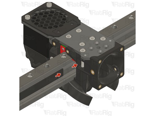
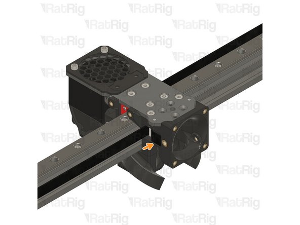
Insert the belt in the designated slot, and ensure the belt end is fed from behind the screw.
-
Pull the belt end and gently place it inside the groove.
-
The belt teeth must be facing the front of the machine.
See my comment on the previous step - put the belt in before the screws
I second this. Its so much easier to stick the belt in then insert the screw. It should say that in the instructions, but I guess they figured you would "figure it out."
Adam F -
A small flat blade screwdriver is handy to push and pull the belt rhrough this confined space. I found it impossible with fingers alone.
-
-
-
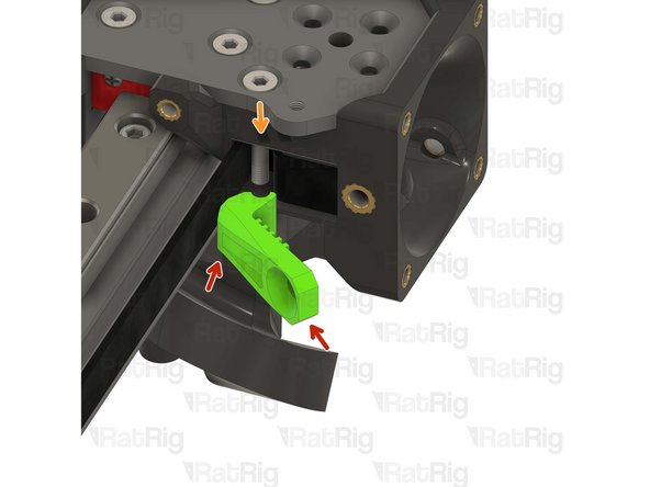
Rat Rig toolhead front belt clamp
-
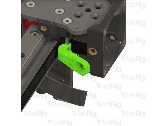
Lever the belt clamp against the exposed screw section and place it inside the belt slot.
-
-
-
1x M4x10 Countersink Screw
-
Tighten the M4x10 screw making sure the teeth of the belt clamp mesh with the belt
-
Pay attention to seating the notch on the belt clamp on the exposed screw section. Pull on the belt to make sure it's secured properly.
-
Repeat Steps 15, 16 and 17 to attach the other belt
-
-
-
Feed the belt inside the slot on the back part of the toolhead.
-
Rat Rig toolhead back belt clamp
-
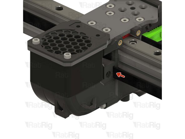
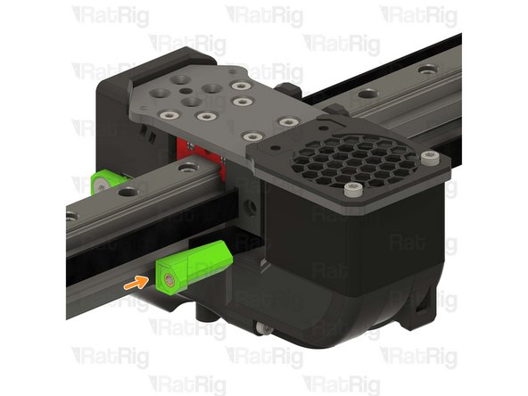
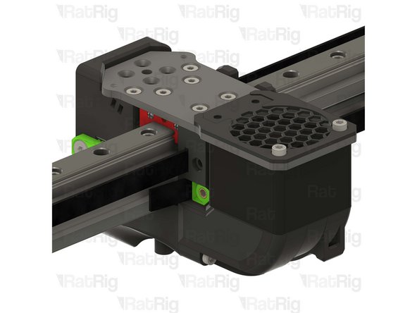
Insert the back belt clamp from the other side of the toolhead, while keeping some excess belt.
First, the wording of 'keeping some excess belt' suggests this is the short end seen in diagram #3, beyond the clamp. However my 400mm kit left me with about 900mm excess belt on each axis, so for me the section beyond the clamp is actually very long. If the 'excess belt' means keep some slack within the active belt, please state that. As written, I don't have a good idea how much slack should be left for the gantry adjustment.
Second, in my set of printed parts with pre-inserted brass threads, the insert left a plug of plastic on the inside of the part, making it very difficult to get the screw to M3x35 CHS to catch from the other side, in step 19. I'd suggest running an M3x35 all the way through the part from the insert side, before installing it, to make sure the hole is clear.
I would second this but take it further: Run a 3mm drill bit through both the tool head back belt clamp and the 'Toolhead-Front'. This makes inserting these bolts very smooth and trouble-free. Technically, ALL holes should be chased with appropriate drills prior to assembly!
Then, before placing the toolhead back belt clamp in its hole, thread in the M3x35 cap screw, directly into the thread insert to ensure that the insert is installed at the correct angle. It needs to be directly aligned with the hole! The shaft of the screw will give a good indication of accuracy. Threading through the plastic part and THEN into the insert could end up damaging the screw and/or the insert if the angle is out of alignment.
Steve -
-
-
-
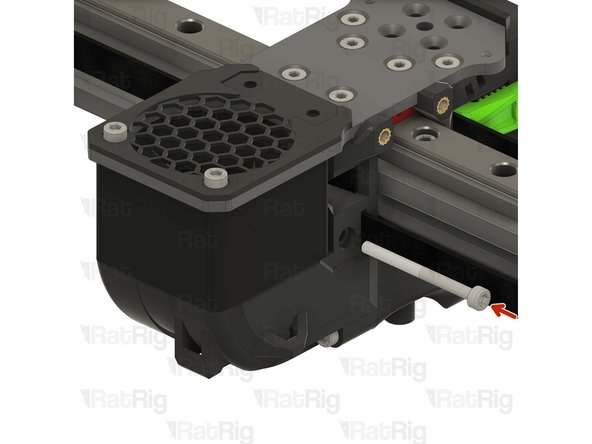
M3x35 Cap Head Screw
-
Tighten the M3x35 Cap Head screw while pulling on the belt from the other side.
-
-
-
Cut the excess belt.
-
Repeat Steps 18, 19 and 20 to attach the other belt.
-
The Hybrid belts will be installed later.
DO NOT CUT THE EXCESS. Wait for the next chapter to align the gantry, it would be a lot easier in case you put too much tension in one belt .
How much of the belt should be sticking out? You say to cut it, but don't specify a target length.
-
-
-
Phaetus Rapido V2 UHF Hotend
-
4x M2.5x6 Countersink Screw
-
PTFE tube - 24.5mm
-
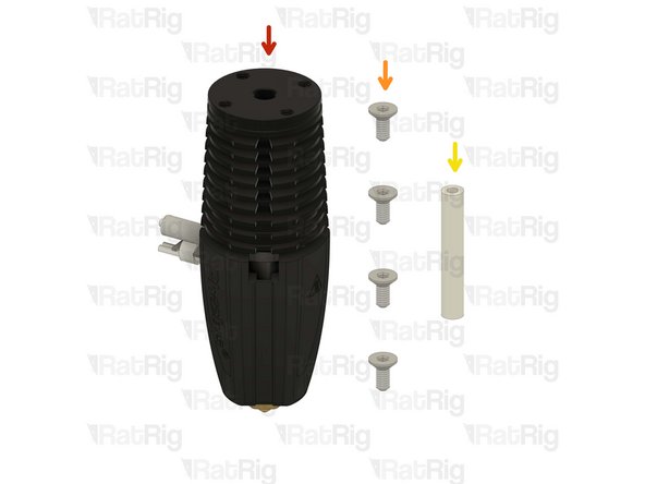
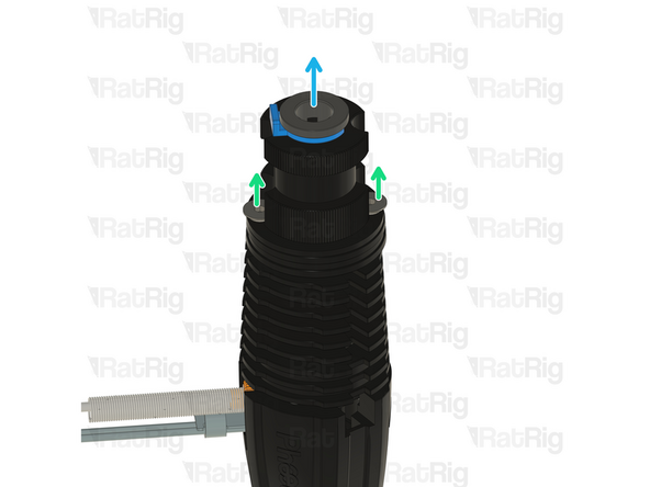
Remove the two countersink screws on top of the rapido
-
Remove the V6-style adapter, it is not required for the RatRig toolhead
One of the heads on the screws was stripped, no way I could get it to loosen. I was able to remove the other with no problem. I tired to turn the V6-style adapter and it would just turn with the one screw removed and the other still tight. I kept working with it and finally got it to spin and was able to remove the stripped screw.
go to chapter 12 before, ***Step 58*** Prepare the Rapido Hotend
and crimp the JST 2 connector, it's time saver
This would be a great point to change and cut the Phaetus wires, while it can still be done as bench work. Doing this later as guided is considerably more effort and opportunity for error.
Thank-you for your comment. You saved my time
+1
-
-
-
Phaetus Rapido V2 UHF
-
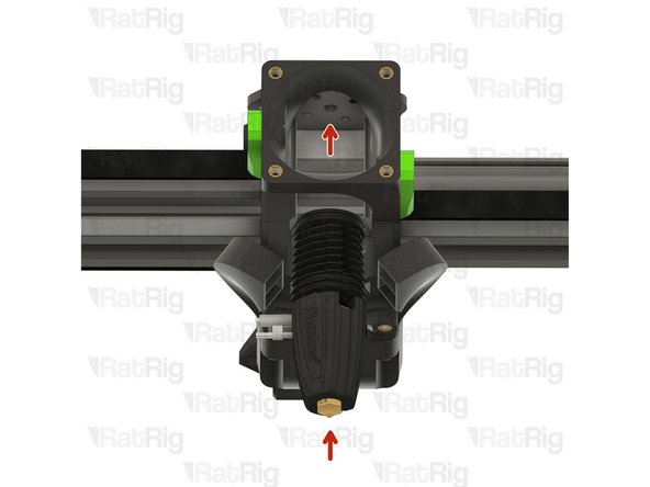
Place the Phaetus Rapido V2 UHF Hotend on the plate, making sure to route the cables through the designated slot
-
Look from above and see if all four holes line up correctly.
-
All the holes on the plate, hotend and printed part should line up:
-
If they align skip to Step 26
-
If they don't align follow the next steps
For reference, the hot tightening procedure is documented here on page 18: Rapido-2F/Instructions Sheet/Rapido Hotend 2 Instruction Sheet.pdf at main · Phaetus/Rapido-2F · GitHub
Basically heat to 285 degrees and tighten to 2.5 Nm.
In the kit, my Phaetus Rapido V2 UHF did not come with a nozzle installed, and there are not any steps in these instructions that actually indicate the nozzle should be installed.
There should be a check that the volcano nozzle is installed here, with diagram before possibly skipping to step 26 and never giving instructions that it's important to use the volcano nozzle instead of the regular nozzle (both of which are included with the phaetus).
+1 here. I think it should be mentioned especially because of the airflow for the part cooling
-
-
-
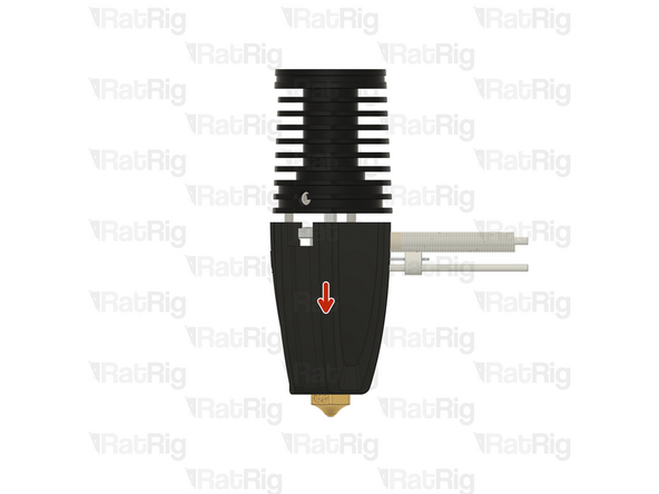
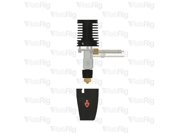
If the cables of your Rapido 2 hotend don't align perfectly with the toolhead slot, please follow the next steps:
-
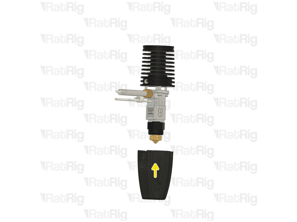
Push down on the silicone sock to remove it
-
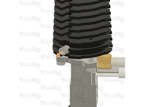
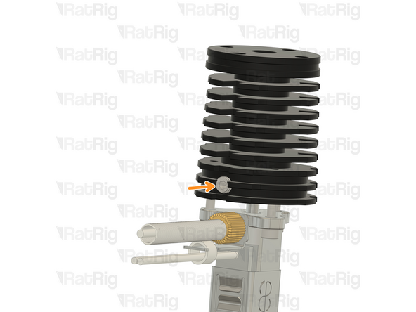
Loosen the set screw on the heatsink
-
Do not remove it completely to avoid losing it
-
-
-
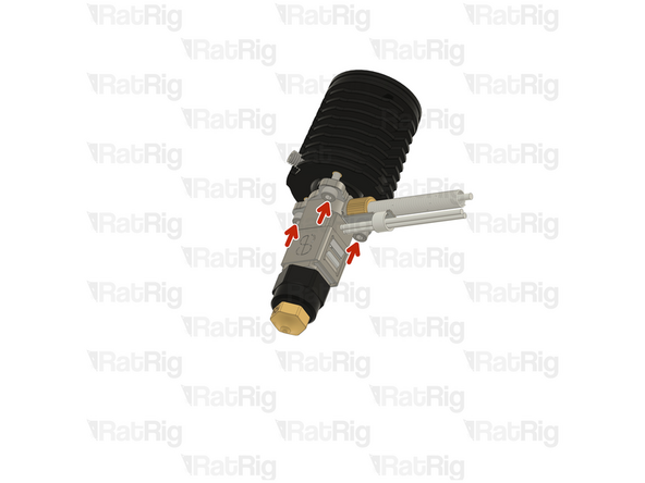
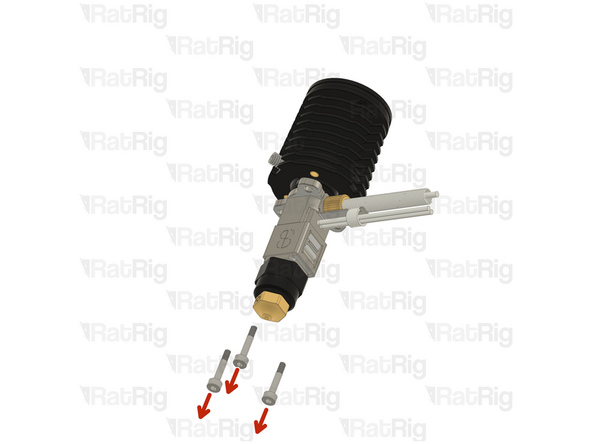
Remove the 2.5mm Cap Head Screws from the hotend
-
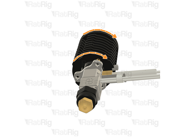
Carefully rotate the heatsink until the three screw holes align again.
-
There isn't a way to tell how much you need to rotate you hotend, it might be just 120º or it might be 240º. It's a matter of trial and error.
-
-
-
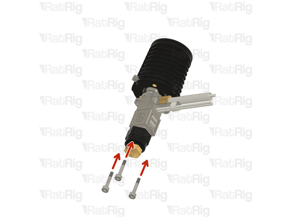
Insert the 2.5mm Cap Head Screws back in and tighten them.
-
DO NOT overtighten the screws, they are only 2.5mm and will break if excessive force is applied.
-
Tighten the set screw back in
-
DO NOT overtighten the screw, if excessive force is applied the heatbreak will be permanently damaged.
-
Put the socket back on
-
Try to insert the hotend on the toolhead and see if the cables align with the designated slot, if not, repeat Steps 23, 24 and 25 and try a different angle in Step 22
-
-
-
4x M2.5x6 Countersink Screw
-
Tighten the M2.5x6 Countersink Screws to secure the hotend to the plate.
-
Avoid using a ball end hex key, as they are more prone to damaging the sensitive M2.5 countersink screw head.
-
PTFE tube - 24.5mm
-
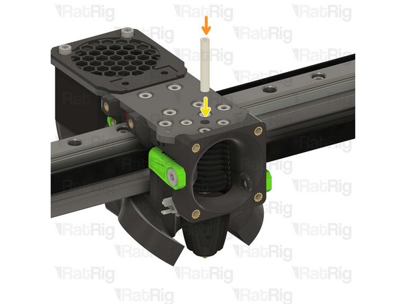
Insert the PTFE tube in to the marked hole and push it until it stops.
-
-
-
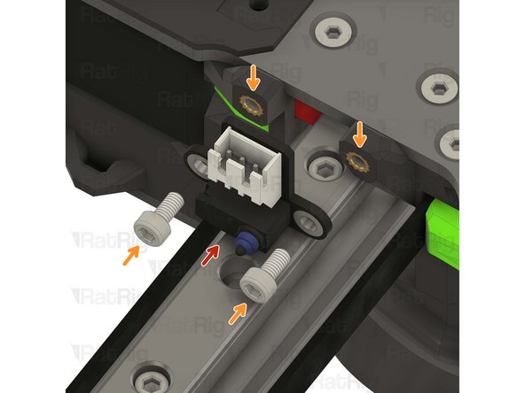
1x Rat Rig Endstop
-
2x M3x6 Cap Head Screw
-
-
-
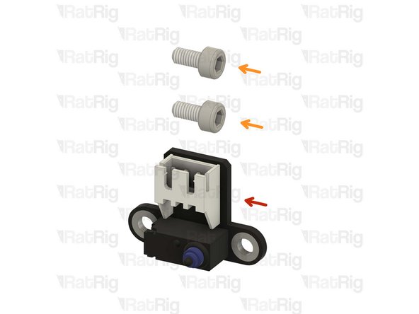
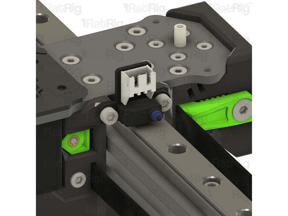
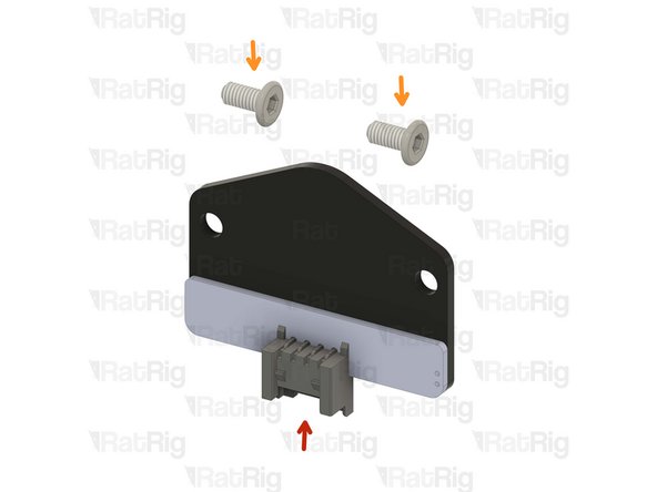
Rat Rig X Endstop
-
2x M3x6 Cap Head Screw
-
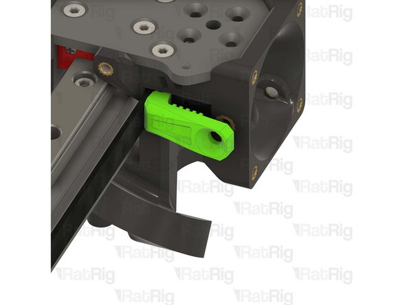
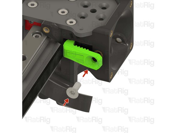
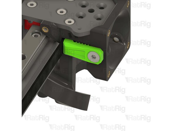
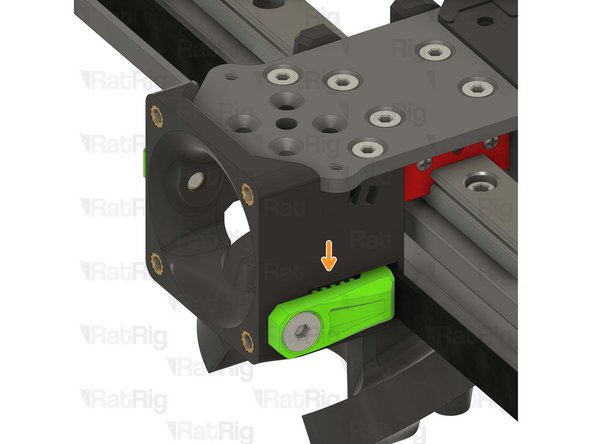
Tighten the M3x6 screws to secure the X endstop to the toolhead.
-
Take care not to over tighten the M3x6 screws as you can damage the printed parts.
-
-
-
1x rr_vc4_toolhead_shroud
-
40x10mm 24V Axial Fan
-
4x M3x16 Cap Head Screw
-
Remove the sacrificial layers from the back of the rr_vc4_toolhead_shroud
-
-
-
Rat Rig toolhead fan shroud printed part
-
40x10mm 24V Axial Fan
-
The wires should be positioned where the arrow points.
-
4x M3x16 Cap Head Screw
-
Insert the M3x16 screws into the Rat Rig toolhead shroud printed part, through the 40mm fan, and fasten them into the Rat Rig toolhead front.
-
Take care not to over tighten the M3x16 screws as you can damage the printed parts.
-
Pay special attention to the fan airflow, it should blow the air towards the hot end heat sink. Most fans have a small arrow indicating the airflow. If not, the the fan label should be facing the hotend.
-
-
-
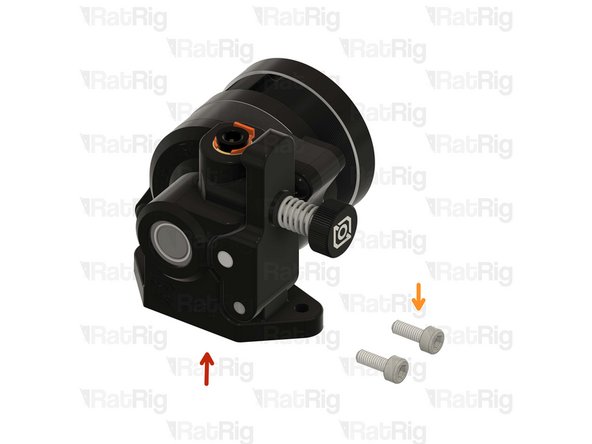
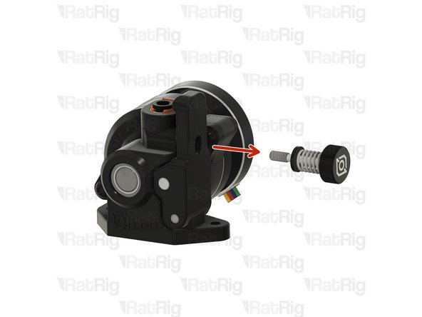
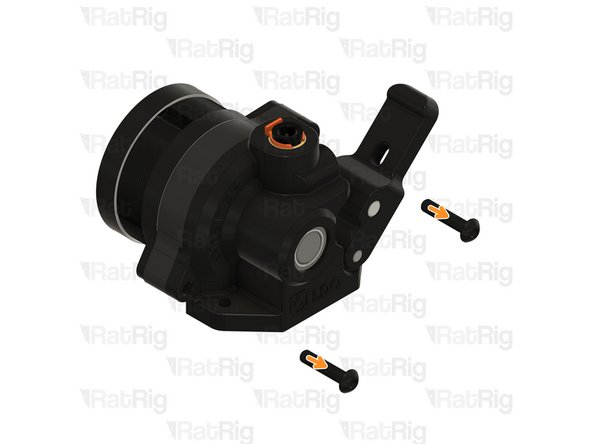
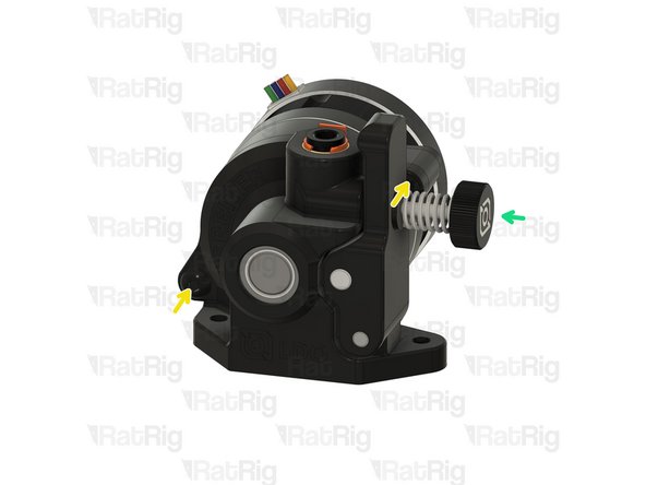
Remove the tensioning screw
-
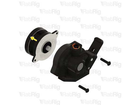
Remove the two front screws
-
Carefully detach (or rotate) the stepper motor from the housing
-
-
-
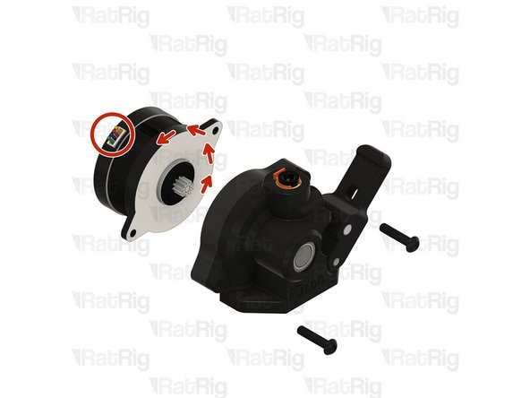
Rotate the stepper motor 180º until the wires come out from the top.
-
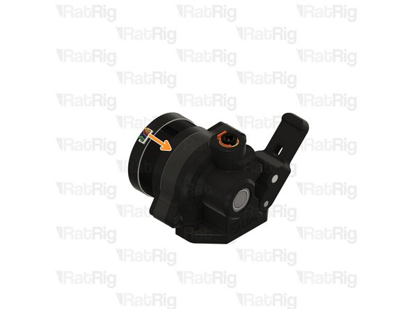
Carefully reinstall the stepper on the housing.
-
Install the front screws
-
Install the tensioning screw
-
-
-
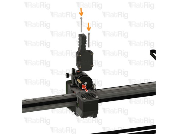
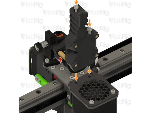
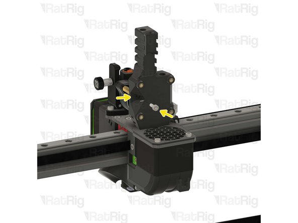
LDO Orbiter V2
-
2x M3x8 Cap Head Screw
-
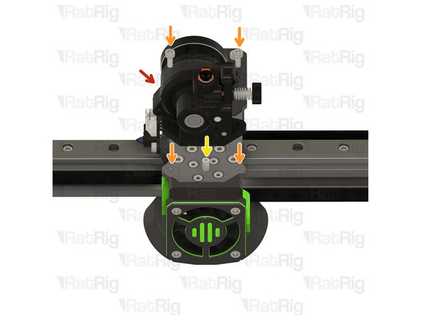
Carefully align the extruder with the PTFE tube.
-
Insert the M3x8 screws into the LDO Orbiter V2 and fasten them to the Rat Rig toolhead plate.
-
Take care not to over tighten the M3x8 screws as you can strip the toolhead plate threads
-
-
-
1x Beacon Rev H Low Profile
-
2x M3x6 Low Head Screw ss304 blk
Where are these screws in the kit? Mine are nowhere to be found. Should they have been included inside bag with the Beacon?
Thanks for the reply, but unfortunately they weren't in there. Closest thing I found (not in that bag but elsewhere) was a pack of button head cap screws, m3x6, and some countersink m3x6's. But no screws in the toolhead hardware pack. Unfortunately pretty sure both of those are carbon steel which I imagine is not going to work with an eddy current scanner. The company I am building the printer for have sourced the screws, not a huge deal. Just thought you might want to know for QA purposes.
Bill -
the screws should be on a bag labeled " Rat Rig V-Core 4.0 - Toolhead v1.0 - Hardware Pack (Orbiter/Rapido)" with the SKU HW3843MK
Rat Rig -
-
-
-
Beacon Rev H Low Profile
-
Rat Rig recommends connecting the beacon's cable before mounting it to ensure the connector is fully and securely inserted.
-
2x M3x6 Wafer Head Screw
-
Tighten the M3x6 screws to secure the Beacon to the toolhead.
-
Take care not to over tighten the M3x6 screws as you can damage the PCB and the printed parts.
-
-
-
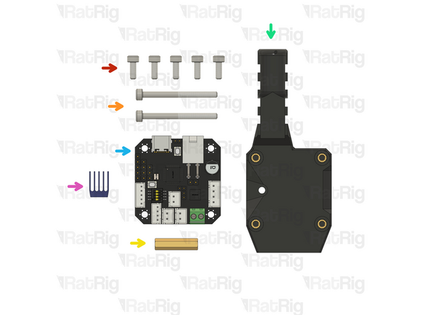
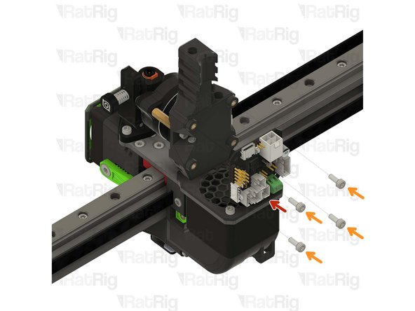
5x M3x8 Cap Head Screw
-
2x M3x35 Cap Head Screw
-
1x Hex standoff M3x20x4.5
-
rr_vc4_toolhead_toolboard_vertical
-
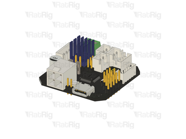
BIGTREETECH EBB42 USB/CAN TOOLBOARD V1.2
-
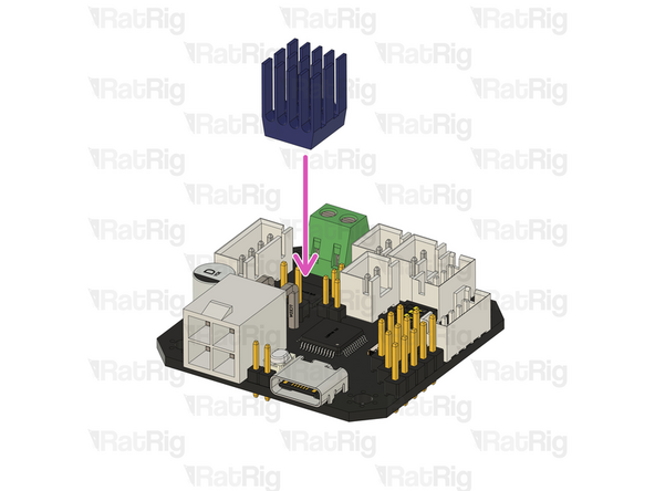
TMC2209 driver heatsink (included in the EBB42 box)
-
Remove the adhesive backing from the heatsink and gently press it onto the TMC2209 driver.
Does anybody know if these USB/CAN toolboards allow for the use of the LDO Orbiter Smart Sensor? I would hope that it would be easy to implement a filament runout sensor, especially when running as an IDEX printer, which is the primary reason why I got this printer.
-
-
-
Thread the hex standoff on to the LDO Orbiter V2 screw.
-
Do not overtighten the hex standoffs. They are brass and it is possible to strip the threads.
-
Insert the M3x35 screws into the Rat Rig toolhead vertical toolboard mount printed part and secure it onto the toolhead.
-
Take care not to over tighten the M3x35 screws as you can damage the printed parts.
-
1x M3x8 Cap Head Screw
-
Insert the M3x8 screw through the printed part and into the thread to attach it to hex standoff.
My kit from Feb 2025 included the Orbiter Smart Sensor and I found it easier to install the sensor before installing the toolhead mount and board: 04. Orbiter Smart Sensor - Rat Rig
It would be nice if those instructions were added or linked here in the official instructions.
Older kits still came without the Orbiter Smart Sensor 2. That also means the Hex standoff M3x20x4.5 is 3mm too long. You need a 17mm standoff to make this work to retrofit the filament sensor.
Of course RatRig doesn't include 17mm standoffs while selling you 2 filament sensors for your V-Core 4. (They don't even tell you that you need them, even when explicitly told that you're buying them for a V-Core 4.)
Newer shipments came with the Orbiter 2 runout sensor. You can find the docs here.
the m3x8 cap head screw should be inserted into the printed part before the m3x35 screw since it intersects with its path
the m3x35 screw that goes trough the entire part requires a ludicrously long hex key, maybe this should appear in the first part of the guide while preparing the tools necessary
-
-
-
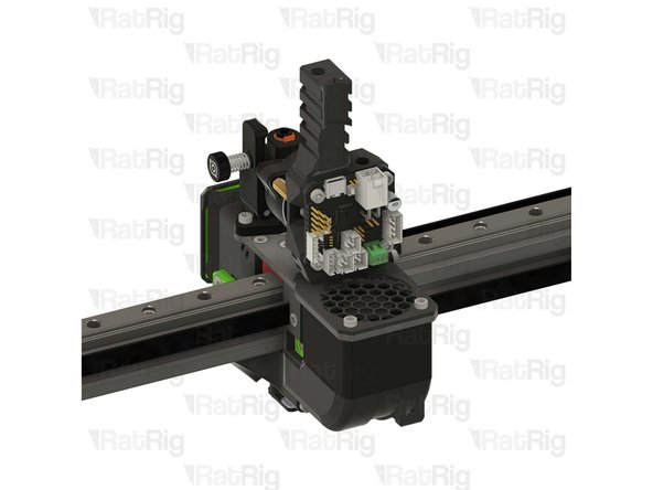
BIGTREETECH EBB42 USB/CAN TOOLBOARD V1.2
-
4x M3x8 Cap Head Screw
-
Insert the M3x8 screws into the toolboard and thread them into the Rat Rig toolhead vertical toolboard mount printed part
This would be a great point to connect the Phaetus power lines to that green connector on the CAN board. It's a wicked tight angle to manage if done later.
Yes! And before you mount the toolboard on the print.
Bill -
Can you please point us to the correct step?
-
-
-
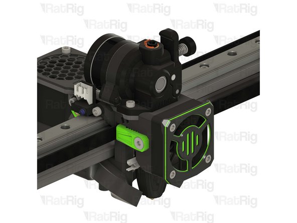
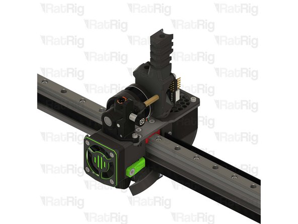
Your V-Core 4 now has the Rat Rig Toolhead installed and it's ready to melt some filament!
-
Cancel: I did not complete this guide.
17 other people completed this guide.
2 Comments
I would have prefered the change of connector being described here and not in chapter 12



There are NO Heat Insert M4 in the kit for step 3. There are not listed in the BOM either
Steve - Reply
The M3 and M4 heat-set inserts are in the Toolhead Hardware pack, which is inside the Toolhead Wiring pack.
Dan Wilson - Reply