
-
-
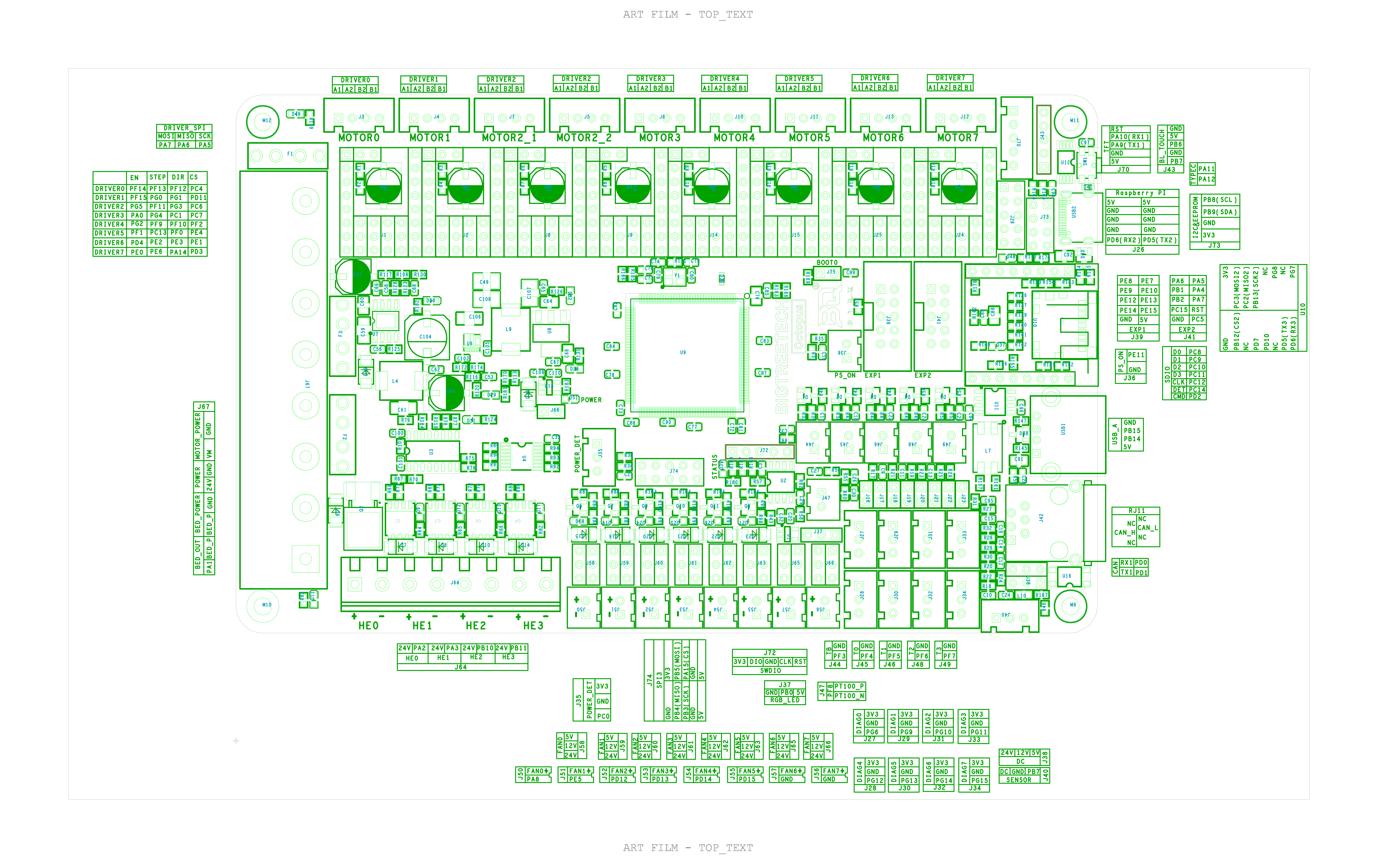
BIGTREETECH Octopus V1.1
-
Raspberry Pi
-
USB A to USB C Cable
-
Insert this jumper, allowing the board to receive power from the Raspberry Pi. Remove all other jumpers from the board.
-
5V Power supply - smartphone charger for example (minimum 3 AMP is recommended)
-
It is heavily recommended that you flash your board and make sure it is detected in the configurator before you plug in your stepper drivers and start connecting your wiring. - Check RatOs documentation
-
Remove the highlighted jumper as it will no longer be required.
-
If your board flashed successfully you can proceed with the guide.
-
-
-
If your kit has a 120mm fan skip this Step and keep following the guide.
-
If your kit has 50x15 axial fans, Identify your electronics enclosure kit
-
If your corners are aluminium, you have the aluminium enclosure - Click here to follow the dedicated guide.
-
You can also check your kit SKU- HW3810MK
-
If your corners are printed parts, you have the steel enclosure, Click here to follow the dedicated guide.
-
You can also check your kit SKU- HW3916MK
I have the aluminum enclosure, but just got the printed corners.
The SKU is misleading, I had the "SKU- HW3810MK" which would mean that I would get aluminium corners but I did not. It simply just should be if you got the corners go to this section else go to the other one.
-
-
-
vc4_enclosure_alum_lid
-
vc4_enclosure_alum_base
-
vc4_enclosure_alum_bottom
-
vc4_enclosure_alum_left
-
vc4_enclosure_alum_top
-
vc4_enclosure_alum_right
-
-
-
vc4_electronics_corner
-
28x M3 Heat Insert
-
31x M3x6 Countersink screw
-
32x M3x6 Button head screw
-
4x M4x10 Countersink screw
-
2x M4x12 Countersink screw
-
4x Hex Standoffs 35mm
-
-
-
vc4_enclosure_alum_base
-
2x M3x6 Countersink screw
-
vc4_electronics_corner
-
Thread the M3x6 countersink screws to the heat inserts on the vc4_electronics_corner.
-
Assemble the components as shown, and ensure the vc4_enclosure_steel_base is correctly oriented and the countersunk screw is inserted into the countersink groove.
-
Repeat the previous Steps and assemble the remaining corners.
To gound all plates I've added o crimps on two opposite edges (front, "left" and "right") on the two side panels and the top one (between heat insert and plate). The bottom plate is screw to the power supply and by that connected (resistence should be checked). The other panels can then be connected via those two edges and some wire. You can connect them to ground via one of the side screw holes in the power supply with small M4 or use the M6 on the edge.
-
-
-
vc4_enclosure_steel_top and right
-
4x M3x6 Button Head Screw for each panel
-
Assemble the enclosure components as shown, making sure the panels are correctly oriented.
-
-
-
vc4_enclosure_steel_left
-
vc4_enclosure_steel_bottom
-
4x M3x6 Button Head Screw for each plate
-
Assemble the enclosure components as shown, making sure the panels are correctly oriented.
At least in Germany that case would be not allowed to be used per default, because all touchable metal parts need to be connected to gound. Usually that's done by "toothed" o ring crimp that "bite" through the outer layer. With that, a loose/broken high voltage wire would trigger the fuse. Resistens between touchable parts and ground on the power socket needs to be checked and should be less than 5 ohm.
The steel bottom plate needs to be changed in the future by adding an Ethernet port so those using wired networking can connect a network cable to the pi. My solution was to modify and print one to hold a panel mounted ethernet extension cable. Now I can plug in a network cable to the pi without having to leave the cover loose to snake a cable inside.
-
-
-
15A fuse
-
Fuse Holder
-
IEC
-
2x M3x12 Cap Head Screws
-
2x M3 locking hex nut
-
-
-
IEC
-
2x M3x12 Countersink screw
-
Fuse holder
-
2x M3 Locking nut
-
Fuse holder nut
@ratrig the cutout for the fuse holder is too large -> the flat spot does not prevent the fuse holder from rotating
It doesn't need to; use your hands! You SHOULD be able to put enough tightening force on it completely by hand to totally strip the plastic threads. Don't over think it!
Steve -
I've got the same problem.
Hunter -
-
-
-
4x M2.5x6 Cap Head Screw
-
4x M3x8 Cap Head Screw
-
26x M3 Heat Insert
-
vc4_adapter_octopus printed part
-
2x vc4_adapter_rpi printed part
-
3x vc4_cable_guide_5 assembly
-
vc4_cable_guide_4 assembly
-
vc4_cable_guide_cross
Unfortunately I didn't twig this and put M3 inserts in for the Pi. No great problem though, just opened the mounting hole on the Pi t0 3.2mm - plenty of clearance.
No M2.5x6 nor M3x8 countersink screws in my kit, RatRig.
I got the 2.5mm heat inserts, but guide didn't mention it.
-
-
-
Insert the countersink screws into the indicated holes, ensuring that the picture is oriented with the countersink holes facing you.
-
vc4_adapter_octopus assembly
-
2x vc4_adapter_rpi assembly
-
Insert the screws from the bottom, passing them through the panel to tighten them into the heat inserts on the supports.
-
-
-
Insert the countersink screws into the indicated holes, ensuring that the picture is oriented with the countersink holes facing you.
-
10x M3x6 Countersink screws
-
vc4_cable_guide_cross
-
vc4_cable_guide_4 assembly
-
3x vc4_cable_guide_5 assembly
-
Insert the screws from the bottom, passing them through the panel to tighten them into the heat inserts on the cable guide parts.
-
-
-
Insert the countersink screws into the indicated holes, ensuring that the picture is oriented with the countersink holes facing you.
-
5x M3x6 Countersink screws
-
5x Hex standoff - steel - M3x35
-
-
-
Fan grille 120mm
-
Fan axial 120x15
-
4x Self tapping screw - Fam - 12mm
-
-
-
4x Self tapping screw - Fam - 12mm
-
Fan grille 120mm
-
Fan axial 120x15
-
Insert the screws from the top, through the fan grille and the enclosure lid and thread them to the fan body.
-
-
-
SSR relay
-
2x M4 Locking hex nut
-
Raspberry pi
-
Octopus V1.1
-
Power Supply Weho - 250Watt 24V - Fanless
-
-
-
Electronics Enclosure assembly
-
SSR 40A480VAC Solid State Relay
-
2x M4x12 Countersink screws
-
Gently open the SSR Relay tabs to access the mounting holes.
-
2x M4 Nylon Locking Nut
-
Tighten the screws to secure the SSR Relay to the electronics enclosure
Terrible design for this SSR mount.
It's a real chore trying to get those lock nuts in place while tightening the M4 screw from the back.
Fix this ASAP, RatRig.
I used the advice in Step 5 and installed the SSR before putting the sides on. Then I used @sschueller advice and put in the bolt on the side that it can slide into, making this a little snug (so the SSR was held in place and didn't rattle during the next step). Then I put in the bolt on the other end with a lock nut, spinning the nut by holding it with my finger tip while rotating the bolt several turns until it reached the nylon insert and I couldn't hold it. Then I jammed one side of a small needle nose pliers into the side of the nut that it wanted to rotate towards, and turned the bolt to tighten it. It took less time to install than to write these instructions. I think this is basically what @victor did, I just added more explanation.
The SSR is mounted with the high voltage side towards the PSU and the low voltage side towards the Octopus board.
Incredibly stupid mounting solution on the SSR. I was able to get it done by using a slim hex-bit extension and pushing from both sides. Not ideal but it worked.
-
-
-
BIGTREETECH Octopus V1.1
-
Remove all the jumpers on the board before starting. Insert the jumpers onto the highlighted pins.
-
UART mode - placing these jumpers will allow for tuning and controlling options on the printer interface.
-
USB-C Power option - with this jumper the board can be powered via USB-C. This will allow you to compile and download the firmware directly to the motherboard using DFU mode, ideal for testing the board.
-
Voltage Selection - Each fan output can be set to one of three different voltages (5V, 12V or 24V) depending on the jumper positions. The third image exemplifies where the pins must be placed to achieve different voltages.
-
The voltage selections used in the guide are for the electronics kit provided by Rat Rig. If using different fans, ensure the voltages are set correctly to avoid damage to components.
The whole section about jumpers is oh so confusing, take them all off, then put some of them back on in different places, not too sure if they all go back on. It would be so much easier to have CLEAR not underexposed picture of the board as it should be configured in each step rather than using generic pictures
Please clarify the use of the "USB Power Option" jumper. Step 1 states to remove it as "It will no longer be needed". Install until the PSU is connected to the board, or something else?
The "USB Power Option" jumper is only needed when powering the Octopus from the Raspberry Pi for initial flashing. It can be removed after initial flashing is complete.
Would you mean the second image (close-up of jumpers and pins)?
Is the second image directing that those specific pins require jumpers as shown?
The second image is for reference only if you are using other fans. For example, if you are using a 4028-fan running at 24V instead of 12V you should put the jumper to the corresponding slot
-
-
-
BIGTREETECH Octopus V1.1 with the jumpers from the previous Step
-
5x TMC2209 Stepper Driver for CoreXY
-
7x TMC2209 Stepper Driver for Hybrid
-
Orient the TMC2209 Stepper Drivers with the two upper pins to the outside of the board.
-
Make sure the drivers are inserted all the way to ensure a reliable connection.
-
Insert the TMC2209 drivers slowly while checking pin alignment to avoid damaging the components.
-
These two drivers are only used on the Hybrid and IDEX configurations
Comparing the two previous illustrations (the last being the board w/jumpers installed as they should be) suggests that I do NOT want to set the jumpers for UART mode?
As far as I can tell, you DO want to set the jumpers for UART mode, and the image used in this step is just a generic rendering not indicative of jumper position.
Hunter -
-
-
-
BigTreeTech Octopus V1.1 Motherboard
-
4x M3x8 Button head screw
-
Insert the M3x8 Cap Head Screws through the Octopus V1.1 Board and tighten it to the vc4_adapter_octopus assembly
-
Take care not to over-tighten the screws as you can damage the board and the printed parts
-
-
-
Raspberry Pi 4B
-
M2.5x6 Cap Head Screws
-
Insert the M2.5x6 Cap Head Screws through the Raspberry Pi Board and tighten it to the vc4_adapter_rpi_assembly
-
Take care not to over-tighten the screws as you can damage the printed parts
IF you are building the IDEX version of the printer, there is a Waveshare USB hub that goes on the Raspberry Pi (shown here - 15. IDEX Accessories), but which would be much easier to do now rather than deinstalling it later.
-
-
-
Power Supply Weho - 250Watt 24V - Fanless
-
4x M4x6 Countersink Screw
-
Mount the power supply as shown, and tighten the screws to secure it to the electronics enclosure.
The included Weho power supply ships with electrolytic capacitors made by CapXon, a well-know maker of inferior capacitors. Since this power supply is affixed to the electronics enclosure from the back using the 4 screws, and those screws are covered up by the rear enclosure panel, replacing this power supply later will involve a ton of disassembly, including taking out all of the wiring from the electronics box. Rather than do that, I replaced the CapXon capacitors with 12,000 hour Nichicon capacitors so that I can eliminate a major source of possible power supply failure. The replacement capacitors are qty 2 Nichicon UCY2D471MHD (470 uF, 200V, 40mm len x 18mm dia x 7.5mm lead spacing) for the input side, and qty 4 Nichicon UHW1V471MPD (470 uF, 35V, 16mm len x 10mm dia x 5mm lead spacing) for the output side. I tested the power supply on a bench load bank after replacement to 120W with no issues.
I think it’d be a useful design feature to add holes to the rear panel to allow access to the power supply and SSR screws. Would make life quite a bit easier if I ever have to replace them for little added cost to the panel. Either that or a different mount mechanism for the PS and SSR (lord knows the SSR needs one), but the PS is already a fairly tight fit.
Jump to step 29 if you don't have the enclosure's back panel.
-
-
-
Jump to Step 29 If you don't have a rear panel.
-
Panel Assembly - Rear
-
1x Adhesive backed foam sealing tape
-
4x vc4_grommet_V1
-
17x T-Nut Drop In for 3030 - M6
-
20x M6x12 Cap Head Screw
-
17x M6 Washer
Where can I get the back panel? Do I have to make the back wall myself? Can I use 4mm acrylic for the back panel and laser cut it (Core 500)?
The screws to hold the rear panel should be about 2mm longer. 12mm is just short enough to be a real pain in the rear.
18 washer, 16 for the outer parts, 2 for inside the plate
A quantity of 17 M6 cap head screws, washers, and T-nuts are used to attach the rear panel, not 16.
-
-
-
Panel Assembly - Rear
-
M6x12 Cap Head Screw
-
M6 Washer
-
T-Nut Drop In for 3030 - M6
-
Insert a M6x12 Screw into a M6 washer through the rear panel, and loosely tighten a T-Nut.
-
Double check the panel orientation, an easy way to make sure is to orient the panel in a position where the marked hole is more to the left than to the right.
-
Insert a vc4_grommet_V1 in each designated hole from the same side as the t-nuts
-
-
-
Install the Adhesive backed foam sealing tape to the outside of the V-Core 4 frame, to ensure a good isolation between the frame and the panel.
-
-
-
Install the rear panel to the V-Core 4 frame
-
Tighten the screws around the panel, to secure it to the frame.
-
Do not over-tighten the screws as you can damage the panel.
-
-
-
Electronics enclosure
-
4x M6x12 Cap Head Screw
-
4x M6 Nylon Locking Nut
-
Insert an M6x12 Screw into the electronics enclosure and the rear panel, and tighten it to an M6 Nylon locking nut, to secure the assembly
-
Do not overtighten the screws as you can damage the panel.
These bolts are too short if you're using a 6mm ACM back panel! A 15mm would probably barely make it to the nylon lock rings, And I personally ran the bolts the opposite direction because I didn't want fugly silver nuts visible on my very nice, clean, black ACM wall!
Im going to replace mine with 20mm bolts and washers once the arrive.
-
-
-
This guide will next tackle the wiring of all the components, which can be a long task. Take a break and have some food.
-
Continue on Step 37 as the next steps will cover the non-enclosed V-Core 4 version
-
-
-
4x M6x12 Cap Head Screw
-
T-Nut Drop In for 3030 - M6
-
vc4_electronics_mount_upper
-
vc4_electronics_mount_lower
-
-
-
vc4_electronics_mount_upper
-
M6x12 Cap Head Screw
-
T-Nut Drop In for 3030 - M6
-
Repeat the previous Steps and prepare another assembly.
-
-
-
vc4_electronics_mount_lower
-
M6x12 Cap Head Screw
-
T-Nut Drop In for 3030 - M6
-
Repeat the previous Steps and prepare another assembly.
-
-
-
Electronics enclosure
-
2x Upper mounting assemblies from Step 45
-
2x M6 Nylon Locking Nut
-
2x M6x12 Cap Head Screw
-
Take care not to over-tighten the screws as you can damage the printed parts
It should say Step 30 not Step 45.
-
-
-
Lower mounting assemblies from Step 46
-
Lightly tighten the screws to secure the assemblies to the V-Core 4 frame, do not fully tighten them as you will need to readjust the height on the next steps.
-
-
-
Electronics enclosure assembly
-
Place the mounting printed parts on top of the 3030 extrusion as shown.
-
Adjust the electronics enclosure from left to right to get it centred on the V-Core 4 frame
-
Tighten the M6x12 Screws to secure the assembly.
-
Take care not to over-tighten the screws as you can damage the printed parts
-
-
-
Adjust the printed parts up and down on the extrusion to align the M6 holes with the ones on the electronics enclosure.
-
Align the holes
-
Insert the M6 Nylon Locking nuts and the M6x12 Cap Head Screws from the other side. Tighten the assembly.
-
Finally, tighten the M6x12 Cap Head Screws on the frame.
-
Take care not to over-tighten the screws as you can damage the printed parts
-
-
-
This guide will next tackle the wiring of all the components, which can be a long task. Take a break and have some food.
-
-
-
16x Fork Terminal - 3.7mm Insulated
-
4x Wire - DC Power - 16AWG RED - 270mm
-
4x Wire - DC Power - 16AWG BLACK - 270mm
-
-
-
Wire - DC Power - 16AWG RED/Black - 270mm
-
Strip 5-7mm of isolation on both ends.
-
Crimp a Fork Terminal - 3.7mm Insulated on each end.
-
Repeat the previous Step and prepare 4 red wires and 4 black wires
-
-
-
Red Wire with two Fork terminals (Length: 270mm)
-
Insert one end on the second slot (numbered 2 on the board) and tighten the screw.
-
Insert the other end on the right slot of the [ +V ] section on the Power Supply and tighten the screw.
-
Black Wire with two Fork terminals (Length: 270mm)
-
Insert one end on the first slot (numbered 1 on the board) and tighten the screw.
-
Insert the other end on the right slot of the [ -V ] section on the Power Supply and tighten the screw.
-
After tightening the screws, pull the wire to make sure it's firmly connected. If the wire releases/moves when pulling, reinsert it and tighten the screw.
-
Route the wires accordingly.
The reference below is now to Step 41 instead of Step 57.
The red and black wires that go to the power supply should connect to the left most pair of positive and negative terminals, not the right most terminals. This will leave room for the wires to reach in Step 57.
-
-
-
Red Wire with two Fork terminals (Length: 270 mm)
-
Insert one end on the fourth slot (numbered 4 on the board) and tighten the screw.
-
Insert the other end on the middle slot of the [ +V ] section on the Power Supply and tighten the screw.
-
Black Wire with two Fork terminals (Length: 270 mm)
-
Insert one end on the third slot (numbered 3 on the board) and tighten the screw.
-
Insert the other end on the middle slot of the [ -V ] section on the Power Supply and tighten the screw.
-
After tightening the screws, pull the wire to make sure it's firmly connected. If the wire releases/moves when pulling, reinsert it and tighten the screw.
-
Route the wires accordingly.
-
-
-
Red Wire with two Fork terminals (Length: 270 mm)
-
Insert one end in the sixth slot (numbered 6 on the board) and tighten the screw.
-
Insert the other end in the left slot of the [ +V ] section on the Power Supply and tighten the screw.
-
Black Wire with two Fork terminals (Length: 270 mm)
-
Insert one end on the fifth slot (numbered 5 on the board) and tighten the screw.
-
Insert the other end on the left slot of the [ -V ] section on the Power Supply and tighten the screw.
-
After tightening the screws, pull the wire to make sure it's firmly connected. If the wire releases/moves when pulling, reinsert it and tighten the screw.
-
Route the wires accordingly.
The reference below is now to Step 39 instead of Step 55.
The red and black wires that go to the power supply should connect to the right most pair of positive and negative terminals, not the left most terminals. This works if you followed the advice in the comment in Step 55.
-
-
-
Red Wire with two Fork terminals (Length: 270 mm)
-
Insert one end on the seventh slot (numbered 7 on the board) and tighten the screw.
-
Insert the other end on the SSR Relay positive terminal (the supplied SSR Relay has the positive terminal next to the red indicator LED)
-
Black Wire with two Fork terminals (Length: 270 mm)
-
Insert one end on the last slot (numbered 8 on the board) and tighten the screw.
-
Insert the other end on the SSR Relay positive terminal.
-
It's crucial that the polarity is correct, incorrect wiring will result in severe damage. Double-check your connections using the images. If you have any doubts about your SSR Relay connections please check the supplier datasheet.
-
After tightening the screws, pull the wire to make sure it's firmly connected. If the wire releases/moves when pulling, reinsert it and tighten the screw.
absolutely. The picture is correct but very bad that it says “crucial” but says plug black into a positive terminal. Plug black into Negative Terminal (#4 on my ssr-40 da)
The instruction above with the blue dot that reads, "Insert the other end on the SSR Relay positive terminal."
should instead say, "Insert the other end on the SSR Relay negative terminal."
-
-
-
Before moving on to the next step, check all the wires. The connections must look like the picture.
-
Double check the polarity is correct with the previous Steps. Always place the wire with POSITIVE ( + V ) polarity in the positive slot on Board and the NEGATIVE ( -V ) with the negative slots on the Board. Incorrect polarity will kill the board
Now that you've connected the octopus to the power supply and assuming you have already loaded ratos firmware onto the board (from earlier in this guide), you should remove the usb c power jumper you set. You will be powering from the 24v power supply from here onward, even for updates which will happen automatically.
-
-
-
Cable - XH JST 2 Pin - 22AWG Short Patch Cable - 150mm
-
Fan 50x15 Axial
-
Connect all the fans to the Rat Rig 3-to-1 XH Splitter - 2 Pin - V1
-
Ensure the Jumper is set to 24V
-
Using the small extension cable, connect the splitter board to the octopus, the connector should be inserted on the third fan connector.
In this step I see all jumpers connected to the fan ports while in the previous steps we were to remove all but the third one.
-
-
-
Y endstop already installed on the V-Core 4
-
Cable 2000mm - 3 Conductor 24AWG - JST XH2.54 to JST XH2.54
-
Connect the cable to the endstop module as shown
-
-
-
32x vc4_wire_clip
-
To install a wire clip, insert one end into the extrusion and rotate it until it clicks into place.
-
Later in the guide, some wires will be routed inside the 3030 extrusions. These clips help retain the wires within the extrusion slots.
Mine were irreparably stuck to the raft. Be prepared with some painters' tape to temporarily hold wires in place and plan for this to be one of your first print tasks out of at least PETG. PLA will likely be too brittle
I found that bending the tabs slightly with pliers made it significantly easier to install.
-
-
-
Warning: Check your cables. Incorrect endstop wiring can damage your board.
-
Rat Rig Omron Y endstop
-
Endstop 3 wire cable - length: 2000 mm
-
Connect the JST3 connector to the shown slot on the octopus board.
-
Route the cable accordingly. Place the cables inside the extrusions to help route them.
-
Use four wire clips prepared in Step 46 at the marked locations. Evenly distribute them along the extrusion.
corrected, thank you
I used the shorter cable instead and the length is perfect. 2000mm is way too much
The 2000 mm cable is way too long for this endstop
-
-
-
The V-Core 4 wiring is slightly different depending on the machine variant:
-
CoreXY - Step 49
-
Hybrid - Step 50
-
-
-
Route the Right [R] Stepper motor cable as shown.
-
Route the Left [L] Stepper motor cable as shown.
-
Connect the Left [L] Stepper motor cable to the lowest slot available on the Octopus Board
-
Connect the Right [R] Stepper motor cable to the second lowest slot available on the Octopus Board
-
Make sure the connectors are oriented correctly with their sockets. The "key" on the connector should align with the "gap" on the sockets.
-
The stepper motor wire colour order does not matter if the cable was supplied in the V-Core 4 kit.
-
Use six wire clips prepared in Step 46 at the marked locations. Evenly distribute them along the extrusion.
-
Proceed with Step 52
Hello, it would be grate to have a cable set wich fits to mount the electronics on the side.
In my workroom the printer is in the corner and i could nott access the elecronig at the rear sind (V4 500)
This is an open-source kit. You have to expect to do the work that's involved in open-source projects!
Steve -
The latest printer.cfg did not match this picture for motor connections on octopus board for hybrid machine. Follow the connections on the printer.cfg instead. In printer.cfg, directions assume you are facing the printer.
Good catch on this one!
Steve -
The images have been corrected, thank you for your feedback!
Rat Rig -
-
-
-
This Step is only meant for the Hybrid and IDEX builds if you are building a V-Core 4 CoreXY skip this Step.
-
Route the L Stepper motor cable as shown. (This will be the X stepper in the idex)
-
Route the R Stepper motor cable as shown. (This will be the DC stepper in the idex)
-
Connect the Left [L] Stepper motor cable to the first slot available on the Octopus Board, counting from the bottom.
-
Connect the Right [R] Stepper motor cable in the sixth slot available on the Octopus Board, counting from the bottom.
-
The stepper motor wire colour order does not matter if the cable was supplied in the V-Core 4 kit.
-
Use three wire clips prepared in Step 46 at the marked locations. Evenly distribute them along the extrusion.
The latest printer.cfg did not match this picture for motor connections on octopus board for hybrid machine. Follow the connections on the printer.cfg instead. In printer.cfg, directions assume you are facing the printer.
The images have been corrected, thank you for your feedback!
Rat Rig -
-
-
-
This Step is only meant for the Hybrid and IDEX builds if you are building a V-Core 4 CoreXY skip this Step.
-
Route the Y1 Stepper motor cable as shown.
-
Route the Y2 Stepper motor cable as shown.
-
Connect the Y1 Stepper motor cable to the second slot available on the Octopus Board, counting from the bottom.
-
Connect the Y2 Stepper motor cable in the fifth slot available on the Octopus Board, counting from the bottom.
-
The stepper motor wire colour order does not matter if the cable was supplied in the V-Core 4 kit.
-
Use three wire clips prepared in Step 46 at the marked locations. Evenly distribute them along the extrusion.
-
Proceed with Step 52
@ratrig this path is not ideal because of the filament guide and the 2 electronic box holders. More ideal is to pass with the wire all the way to the bottom of the extrusion ( right next to the motors ) and guide the wires through the same path as the previous steppers.
It would be nice if the filament guide and electronics box holder were integrated into one piece. No obstruction of the bottom hollow for wire routing. I'm taking my hybrid motor wires up and over to the middle, and then down into the electronics box. I figure the motor wires can get their own textile sleeve and then wire tied with the rest of the cables coming from the extruder heads.
I see what you're saying, but, at least in the case of an enclosed system that means the wires will be in danger of rubbing against the belts in the back as the wire goes from above to below the frame bar. I'm inclined to agree with you and am going to try using those lower holes and put some wiring loom material to keep the wires away from the belts.
Scott -
In the second image above, the Y1 (dark blue) motor cable is shown going to the 6th connector, but it should go to the 2nd connector.
@ratrig is this correct ?
-
-
-
Stepper Motor Wire
-
Front Z Steppers cables 1500mm
-
Rear Z Stepper cable 1000mm
-
Stepper Motor Connector (wider connector / JST PH6P)
-
Control Board Connector (narrower connector / JST XH2.54 )
-
Make sure the connectors are oriented correctly with their sockets. The "key" on the connector should align with the "gap" on the sockets.
-
Connect all the Z Stepper motor cables, ensuring the longer 1500 mm are used for the front Z steppers and the shorter 1000 mm is used for the rear stepper motor.
-
The stepper motor wire colour order does not matter if the cable was supplied in the V-Core 4 kit.
-
-
-
If your bottom panel has a grommet dedicated to the Z Steppers, follow here, otherwise, skip this Step.
-
Route the Z0 Stepper motor as shown
-
Route the Z1 Stepper motor as shown
-
Route the Z2 Stepper motor as shown
-
Feed all the cables through the bottom panel grommet.
-
Feed all the cables through the rear panel grommet and into the electronics enclosure
-
Connect all the cables to the octopus board as shown; Z0 - driver 5; Z1 - driver 6; Z2 - driver 7;
-
Use eighteen wire clips prepared in Step 46 at the marked locations. Evenly distribute them along the extrusion. Four of them should be used on the vertical rear Z extrusion.
Feels like this wire routing would have been far, far easier to accomplish prior to doing any X gantry or bed mounting, leaving the wires laying on top of the bottom plate.
Also the directions install the hotend and all the parts. Then later you need to go back, cut off then ends and crimp correct ones. It would be much easier to do this sitting at a bench before installing any of it.
Instructions say steppers should go in slots 5,6,7, the image shows 7,8,9.
I followed 7,8,9 as 5,6,7 conflicts with previous instructions
The colors used in the diagrams are con fusing especially the first. The light green and the aqua are different wires. I thought they were the same color and same wire. I'm old and not very good with colors!
Quoting for helpfulness:
The Z0 Stepper must be connecter to driver 6.
Z0 is the front left stepper, when looking at the machine from the front.
The Z1 Stepper must be connecter to driver 7.
Z1 is the rear stepper, when looking at the machine from the front.
The Z2 Stepper must be connecter to driver 8.
Z2 is the front right stepper, when looking at the machine from the front.
Would be good to specify also instead of Z0, Z1 and Z2 the location of the steppers like Left, Right and Middle. Would make it easier to trace cables
@ratrig If the electronics box is mounted on the frame ( without enclosure ) the path is not ideal cause the wires would have to pass over the mount for electronics box. Since the electronics box is not heavy and it's not going anywhere, I would remove just the M6*12 screw and drop in T-Nut 3030 M6 and keep the plastic part on the enclosure box. This will not hinder the stability of the electronics box and will give room for the wires to be passed as shown in the picture. And then it will also look good visually ;)
-
-
-
If your bottom panel has a grommet dedicated to the Z Steppers, follow here, otherwise, go back to the previous Step.
-
Route the Z0 Stepper motor as shown
-
Route the Z1 Stepper motor as shown
-
Route the Z2 Stepper motor as shown
-
Feed all the cables through the bottom panel grommet.
-
Feed all the cables through the rear panel grommet and into the electronics enclosure
-
Connect all the cables to the octopus board as shown; Z0 - driver 5; Z1 - driver 6; Z2 - driver 7;
-
Use eighteen wire clips prepared in Step 61 at the marked locations. Evenly distribute them along the extrusion. Four of them should be used on the vertical rear Z extrusion.
-
-
-
The Z0 Stepper must be connecter to driver 5.
-
Z0 is the front left stepper, when looking at the machine from the front.
-
The Z1 Stepper must be connecter to driver 6.
-
Z1 is the rear stepper, when looking at the machine from the front.
-
The Z2 Stepper must be connecter to driver 7.
-
Z2 is the rear stepper, when looking at the machine from the front.
It's a little disappointing that the error of the Z1 & Z2 motor locations was pointed out in Aug., and here it is almost Dec. and it has yet to be corrected. Fortunately, there are some wonderful people here in the comments that, without their contributions to this guide, have saved me from making some critical errors, which this guide is supposed to prevent.
The Z0 Stepper must be connecter to driver 6.
Z0 is the front left stepper, when looking at the machine from the front.
The Z1 Stepper must be connecter to driver 7.
Z1 is the rear stepper, when looking at the machine from the front.
The Z2 Stepper must be connecter to driver 8.
Z2 is the front right stepper, when looking at the machine from the front.
Technically it is 5 6 and 7 because the octopus shares two outputs at motor 2. So the octopus can control 8 different motors, and one of them can control two (but with identical commands) but in this case the drivers are labelled: 0, 1, 2, 2A, 3, 4, 5, 6, 7.
Bill -
-
-
-
The Raspberry Pi wiring is the same regardless of the Raspberry Pi model used. Please note that all GPIOs are in the same place as well as the USB ports.
-
Power Input +5V
-
Power Input GND
-
Black Jumper Wire ( Length: 500mm )
-
Red Jumper Wire ( Length: 500mm )
-
USB A to USB C Wire - Provided with the octopus board
-
The Raspberry Pi can be powered in many ways, using an external 5V power supply, via USB (power input) and via the GPIOS pins. The V-Core chooses to power the PI via the GPIOS pins as this simplifies the wiring.
-
-
-
Red and Black Jumper Wires ( Length: 500mm )
-
Red Wire- Power Output +5V on the Octopus V1.1
-
Red Wire- Power Input +5V on the Raspberry Pi
-
Black Wire- Power Output GND on the Octopus V1.1
-
Black Wire- Power Input GND on the Raspberry Pi
-
USB A to USB C Cable
-
Connect the USB A Port on the Raspberry Pi and the USB C Port on the Octopus V1.1
The two images show different connections for the RPi power lines for where to attach on the Octopus board, The close up image shows black/negative beside the red line. The high view image shows the negative line above the red line.
nvm i'm dumb... look up the pinout of the btt octopus 1.1 board and you will understand... maybe... i'm still a noob (this is for whoever reads this like me) https://teamgloomy.github.io/images/btt_...
wait can you disambiguate what you're saying here. my interpretation of what you are saying is "do not connect as illustrated in the second picture with the individual black and red lines and do it as illustrated the first picture?" is that correct?
sorry i was trying to reply to arto here
Looking at the pinout I think that is the J26 connector, which has 5V pin at the end (pins 1 and 2 I think) and next pins are 0V. The connection in the second picture is probably not a good idea.
Checked with a multimeter to be sure. The first two pins at the end of the connector are shorted, those are both 5V. Next 6 pins in the middle are all 0V. Two pins at the other end are UART it seems.
Arto -
The power wires are rather flimsy. They would be a lot better if they were both connected. This would give them support and prevent twisting
-
-
-
Phaetus Rapido V2 UHF Hotend
-
RED WIRE - Cut the wires with 150mm and strip 5-10mm of the end, to expose the inside conductor.
-
BLUE WIRE - Cut the thermistor wires with 160mm and crimp a JST 2 connector
-
The thermistor is a resistor that strongly varies with temperature. When crimping a resistor you don't have to worry about wire order as resistors don't have polarity.
It appears there might be a translation issue here. The wording for the step should be corrected to...
RED WIRE - Cut the wires to 150mm and strip 5-10mm of the end to expose the inside conductor.
BLUE WIRE - Cut the thermistor wires to 160mm and crimp a JST 2 connector
As for all the talk about having to make wire- this is absolutely pathetic! This is a 100% open source printer that you bought as a KIT!! Literally everything about this build is about YOU putting it together, YOU tuning it, YOU modding it to your needs and preferences, and YOU using it! Expecting, or in some cases demanding, that wires be pre-cut (you really cant cut a wire?) and "properly" terminated is pathetic! Im not using the supplied EBB-42 board, so if all those wires and connectors were made to fit the prescribed board Ide be screw! That would mean I would likely have to replace the extruder, stepper, hot-end, beacon wires, and fans because I want a better $35 board. A completely asinine expectation! If you cant build then don't buy!
the laziness of the documentations for a machine of this price is criminal. @ratrig your reputation for good machines is fading with every step.. if my return window was still open id be sending this back.. $4k Canadian + import fees. for mislabeled documentation horrid wiring schematics and half complete low grade harness is DISGUSTING
Another component that doesn't come with the correct connectors. Another opportunity to damage parts.
If you're struggling hard with crimping tiny connectors, like I do:
There are adapter cables in the toolboard box provided by BigTreeTech. These can be used to make correc tconnection.
They're unsuitable for mounting on the toolheads directly to connect the hotend to the toolboard because the cables are 2m long. (They're meant for connecting to a controller not on the toolhead.) Using these cables adds 40g to you r toolhead and a mounting problem for 4m of cable bunch. → Not a viable option for printing.
@ratrig Please provide short adapter cables that can actually be used without having to crimp another wrong connector. I'd even buy them just to avoid crimping.
@ratrig please update this image as stated before the heater cables are RED. There was already a user on the unofficial discord that got confused because of this
@ratrig Diagram is confusing. In Rapido 2 heater cables are RED and the PT1000 are BLUE. This can lead to burning of the PT1000 if people are not careful
-
-
-
Hot End Heater 24V RED WIRE (The wire colors in the wiring diagram do not accurately represent actual wire colors used in practice.)
-
Insert the cable ends on the designated slots and tighten the screws.
-
After tightening the screws, pull the cable to make sure it's firmly connected. If the cable releases/moves when pulling, reinsert it and tighten the screw.
-
Hot End Thermistor BLUE WIRE (The wire colors in the wiring diagram do not accurately represent actual wire colors used in practice.)
-
Plug the connector into the designated connector.
-
The thermistor wires are very fragile, bending them past its threshold can damage the conductors within, leading to wire failure.
-
Insert the highlighted jumper to achieve more accurate temperature readings
-
Route the wires accordingly.
Instructing people to insert stranded wire directly into a screw terminal on a 24V circuit is a fire hazard. Stranded wire will collapse under the screw terminal's compression, causing the connection to loosen over time. This can lead to a short, potentially resulting in a fire. Screw terminals require ferrules—but in this design, there's no way to fit ferrules into the terminal due to the limited spacing between the board and the top face of the fan shroud. If I had designed this, I would be quite ashamed and embarrassed.
In Canada, the Canadian Electrical Code (CEC) Rule 12-116 requires stranded conductors to be properly confined to prevent stray strands from causing shorts or ground faults. While ferrules aren’t explicitly mandated, failing to secure stranded wire properly is a clear safety issue.
In the EU, IEC 60204-1 and DIN VDE 0100 set safety standards for electrical connections, strongly recommending ferrules for stranded wire to ensure a secure, compliant termination. Many EU countries enforce this as part of electrical safety regulations.
This design fails both safety standards and regulatory compliance—completely unacceptable.
Jesse C -
Thanks for the warnings, I did this before mounting the hotend, and practiced trimming the thermistor insulation on the waste end. My wire stripper did not work to remove the insulation. I found that a razer knife (Exacto) worked best. I spread the fibers off to the side and trimmed them to expose the center conductor.
@ratrig please update this image as stated the heater cables are RED
It really a pain in the ass to crim this! The most hardest part of the whole build. Please provide the right connectors for future customers!
I totally second that frustraton.
RatRig should also provide a way to replace the wrong connectors for existing customers. (Even if for a small hanling fee.)
MacLemon -
While I also have no love for JST connectors, would this not be easier all around if we took off (or didn't yet install) the EBB board? Getting the heater wires to make a right angle entry from a closed off space seems needlessly challenging. I have to think there's an easier way of getting these steps done.
I did take off the EBB board to install the heater wires. No way I could be sure they are properly in place without taking it off. This part could have been done when we first installed the board.
Arto -
@ratrig Diagram is confusing. In Rapido 2 heater cables are RED and the PT1000 are BLUE. This can lead to burning of the PT1000 if people are not careful
This step of connecting the Rapido blue cables to the EBB board is nearly impossible with the EBB mounted. Best would be to do this before to make sure the wires sit properly and that there are no strands to create a short circuit
It is really a pitty that the good pre-manufactured hotend connectors actually need to be clipped off just to put on a cheap and wobbly JST-connector. I don't get the point here. Why does RatRig not make sure the proper plugs are available on the little EBB32 board or provide a proper ready-made cable set? It is cumbersome and error-prone to crimp this stuff all by myself. Uneccessary step from my perspective.
6 months later, and not only has the connector issue not been resolved, the documentation hasn't been fixed either.
The whole problem could be easily, and reliably, solved by including a short adapter cable for connecting the hotend and thermistor to the toolboard.
MacLemon -
Because they don't manufacture the EBB board, BTT does. It's a 3rd part part they have incorporated into the printer, same as the hotend and extruder are 3rd part parts.
-
-
-
Connect the orbiter extruder cable to the designated slot on the toolboard
-
Route the wires accordingly.
-
-
-
Hot End 4010 fan - 24V
-
Connect the positive and negative wires to the referred slot.
-
Route the cable accordingly.
-
Use a zip tie to ensure the cable is secure to the toolhead body.
-
-
-
Cable 120mm - 3 Conductor 24AWG - JST XH2.54 male to Bare wire
-
Micro JST 5pins provided with the EBB42 Toolboard package
-
Crimp the connector on the 3 wires as shown.
-
Refer to this picture to clearly show where the wires go
I bought a kit on amazon that came with a bunch of connector shells (XH and PH) and bunch of 160mm wires with XH pins on one end and PH pins on the other. I was able to snap this cable together and install in less than a minute... well worth the price.
The iCrimp SN-2549 has the proper die for crimping this connector, it's the smallest one on the very end of the tool. https://www.amazon.com/IWISS-Crimping-AW...
Clarification on the EBB42 Endstop Connector
If you’ve failed or lost your connector, I’ve finally figured out which type it is. The previous documentation is incorrect and cost me several bucks trying to order the correct size. The EBB42 endstop connector uses a PHA-2 connector and not a JST 1.25(micro jst)
This document contains misleading information, so don’t make the same mistake I did. If you need to order a new crimp set or pre-crimped wires, just order PHA-2 pre-crimped wire.
In my package 5-pin connectors were black
ok to be clear (after crushed the whole after mutliple trials..)the cable provide is a jst 2.54 3 wires, you need to pass to eb42 which is a JST 1.25mm pitch which is super fragile and not easy to use .
If you want to do it you need like an iwiss/icrimp 2820M with super small die : 0.7 and 1.0 mm ,
But it's an hell you will propably destroy it ifyou ar enot use to those super small size. The far more easier way is to buy pre crimp 5 wire JST 1.25 and put the 3 JST-xh 2.54 expected at teh other end way way way more easier.
Don't even knwo how ratrig provide the esier crump and expect you to manage this specific difficult small crimp despite you can buy easily pre cirmp wire??
https://www.digikey.be/en/products/detai... seem the rigth one
mrpomme -
be carefull its not 1.25gh neither (learned at my cost...), they are company who sell specifically those shitt cable here for instance : https://3dkatten.eu/products/micro-jst-1...
mrpomme -
Yeah the small crimping is annoying kept messing up. Like you said I’m probably just gonna order the pre crimped one and just get it over with. I’m just wondering though does it have to be 24awg wire or can it be 22awg because I can only find pre crimped 22awg. If you or anyone knows
Manny -
My EBB42 toolbar package come with a 4 pin connector, it still fits but just need to be sure its covering the right connectors
@ratrig Listen, its really not a problem to ship the correct cable. Expecting a user to have all the tools and skill not to completely destroy these tiny connectors isn't really plausible, if you were able to ship one end of the connector ready, there is no reason why the other end should be prepared manually.
i agree even if i crimp some and well toolled those micro a re pure $@$* to handle
mrpomme -
-
-
-
Warning: Check your cables. Incorrect endstop wiring can damage your board.
-
Rat Rig Omron X endstop
-
Endstop 3 wire cable - Prepared previously.
-
Connect the JST3 connector to the shown slot on the toolboard.
-
Route the cable accordingly.
This appears to have changed from previous versions (hence 'check your cables'). I'd like to suggest the wire colors should match the pinout for the EBB42 Endstop -- that seems higher priority that wire colors for a microswitch.
I'm not sure where it would go, but some statement in the commissioning guide of 'if your EBB42 crashes/shorts when the endstop is triggered/released, check the endstop wiring' would have been appreciated.
-
-
-
4x Crimp - Molex Micro-Fit (43025 compatible)
-
Connector - Molex Micro-Fit - 4 Pin - Male (43025-0400)
-
3x Crimp - Molex Micro-Fit (43020 compatible)
-
Connector - Molex Micro-Fit - 4 Pin - Female (43020-0400)
-
2x Connector - 2 Pin - JST XHP-2 - 2.54 Male
-
4x Crimp - JST XH 2.54
-
Cable 1500mm - 3 Conductor 24AWG - JST XH2.54 to JST XH2.54
I would highly recommend wiring this before installing the fans on the printer. Same goes for the other connections, it would be significantly easier to do on the bench than up in the air on the printer.
A little late now eh lol
Jesse C -
Connector - Molex Micro-Fit - 4 Pin - Female (43020-0400) can be easily unolunt with a small srew driver.
you gain 3 crimp in step 67
This step could use a bit more explanation cause it's hard to understand it all the way it's explained
What is unclear to me here is the 1500 mm long cable. What do I need to do with it? It has two JST-XH2.52 connectors, fine. But what now? Clip them also off? Even in the following steps there is no explanation what exactly you want me to do. This part of the build manual is very confusing over all. I read it few times but multiple times missing explanations or some advice what to do.
All my cables are actually twisted and hence, does not correspond to the pictures shown. It is just confusing.
-
-
-
Crimp the Connector - Molex Micro-Fit (43025 compatible) to all the 4028 wires
-
The small tab must be facing upwards.
-
Insert the crimps inside the Connector - Molex Micro-Fit - 4 Pin - Male (43025-0400) as shown
-
1 - 12V Red - NIDEC fan
-
2- GND Black - NIDEC fan
-
3- PWM Blue - NIDEC fan or Brown - Sanyo fan
-
4- Tac White -NIDEC fan (not used with the Octopus board)
-
Insert the crimp on the connector until you hear a "Click"
I too can only confirm very clearly what some have already written here before me:
The assembly was fun until the beginning of chapter 12. There are a lot of wrong or misleading descriptions here, the material lists are incorrect and the lack of these small pins as a reserve cost me at least 2 days until I had a replacement
Very, very annoying
I'm also annoyed that I couldn't do all this cable work before assembling the toolhead and I'm pretty sure that there are easier and more reliable ways to achieve this - for laymen.
Just ordered a set of spare pins on Amazon here... really wish there were a few spares.
No spare crimps.... very ANGRY....
yeap, I had to resolve using soldering
The picture is so confusing. You need to read carefully the text and replace in your mind the colors otherwise you end up swapping wires. Also, I see no mention of cutting the existing connector from the 4028 fan @ratrig
This step is so painful, it's crazy. I don't mind crimping things but I do hate to crip it in place instead of crimping it easier on a bench top. Also, it would not hurt to give 1-2 extra connectors in case someone does it wring once
Again, why all this cut off the exising connectors and crimping stuff? So many parts are delivered with a proper connector. Why does RatRig not provide the proper plugs on its EBB32 board? I don't get it. It becomes really annoying from the build experience perspective.
Cable colors of my 4-wire fan cable does not match the picture.
Also missing proper and EARLY hints in the mechanical kit assembly documentation that some parts (like all the parts affected by this crimping marathon) should be better prepared for wiring BEFORE the assembly of those parts. I have mounted everything as per the description and now struggle to get all those cables crimped while these parts are mounted. :(
Agree!! It's absolutely insane that we would have to build the cable to run the 3D printer that we are... building!
Wait... nevermind
Steve -
The EBB is not a Ratrig part - it is a BTT part. Not sure how feasible it is for them to get a special version just for the VCore 4.
Agreed on recrimping these wires BEFORE assembling the toolhead. Hard to do it installed.
Victor -
-
-
-
Cut the JST3 connectors on the Endstop cable and crimp the Molex Micro-Fit (43020 compatible)
-
Insert them into the Connector - Molex Micro-Fit - 4 Pin - Female (43020-0400) as shown on the images
-
The small lock piece on the connector must be facing upwards.
-
-
-
Use the full length of the RED and Black wires
-
2 Pin - JST XHP-2 - 2.54 Male
-
Crimp the GND (Black) wire to the left slot on the housing
-
Crimp the +12V (RED) wire to the left slot on the housing
-
Cut the white wire with 70mm, measuring from the Molex connector
-
2 Pin - JST XHP-2 - 2.54 Male
-
Crimp the PWM (White) wire to the left slot on the housing
-
Triple check all connections and crimps
Below are the wire colors for all 4028 fans that RatRig currently sells. In all instances, Sensor is unused
Sanyo Wire Description...
Black - 0V
Red - 12V
Brown - PWM (Control)
Yellow - Sensor (Speed-Tachometer)
Nidec Wire Description...
Black - 0V
Red - 12V
Blue - PWM (Control)
White - Sensor (Speed-Tachometer)
Protechnic Wire Description...
Black - 0V
Red - 12V
Blue - PWM (Control)
Yellow - Sensor (Speed-Tachometer)
Delta Wire Description...
Black - 0V
Red - 12V
Blue - PWM (Control)
Yellow - Sensor (Speed-Tachometer)
Guys, this is an easy one.It took me a while to realize that there are 3 long JST 3-pole cables included.
(Cable 1500mm - 3 Conductor 24AWG - JST XH2.54 to JST XH2.54)
All i did was to cut off the part with the white wires. So i had a 2-pole connector for the cooling part fans. Watch out for polarity though, the cable ends are different. As the white wire was left over i used this to connect to the blue wire of the fan. No crimping here at all.
Michael.
I have other vcores and yes the fan turns on at 100% when I power on because it's wired like this. But I actually like it, because I know when the printer is fully booted up without looking at my computer or phone, because the fan shuts off at that time. Also my vcores are enclosed and if you have the enclosure fully closed up at power on, it's relatively quiet.
You should include a summary of what you are trying to achieve (with all of these connectors). See mine below. You need a schematic of the wiring from the toolhead to the toolboard and the printer board all on one diagram. Also name the four cables exiting from the fan; 12v, Ground, PWM and Tachometer instead of using colors since they vary.
You want to make the 4028 more easily swappable (in case of failure) by replacing the existing connector, cutting the remaining cable short (40mm?) and adding the 4 pin male and female connectors between the fan, the toolboard, and the printer board. You need to connect to both the printer board and the toolboard because the toolboard can't supply 12v to the fan (and these types of fans are not widely available in a voltage the toolboard can supply). The toolboard can only connect pwm for this fan. So you need the printer board for 12v, ground and the tachometer (optional). IMO it makes more sense to use 1 connector pair, and send all four cables to the printer board.
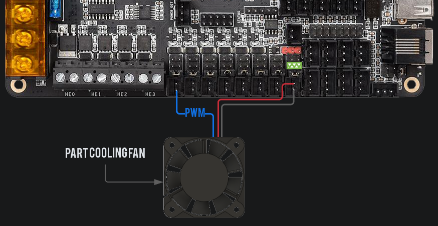
The printer.cfg set up for for the octopus board doesn't assume you put the PWM wire to the tool head.
It assumes that you actually used the last fan slot for the PWM as shown here: https://os.ratrig.com/assets/images/4028...
Advise not connecting it like this, else the fan will spin at 100% while the printer boots.
See my comment in step 68 - At this point, do not crimp the -ve wire to the JST-XH 2 pin, leave it bare
So here's a confusing color matter- earlier it says the yellow (in my case white) line out from the fan is not used on the Octopus board. Then the image that follows shows a white wire coming out of position #3. That means that the blue line out from the fan in block position #3 will be what now connects to a white wire. Probably it'd be good to say so. If you are simply thinking of connectivity, you'd probably think red to red, black to black, and white to white, not white to blue which is what you're really doing with connection #3.
The images above could be enhanced by the use of "break lines" across the red and black wires, to indicate that they are much, much longer than what's shown in the images. In my 300mm bed size kit, I had 1000mm and 1500mm cables to choose from.
What cable is used in the picture? There is no explanation about which cable is meant here. Is it the cable shown in step 80 above, which already has two connectors on both ends? Do I need to also cut them off? There is no explanation.
What is the recommended length of the white cable? It looks much shorter than the red and black ones...
The instruction above with the green dot reads, "Crimp the +12V (RED) wire to the left slot on the housing"
but it should read "right slot."
Depends which way you are looking. The picture is correct but text is rubbish. Yellow arrow is pointing at red wire but text says black.
Arto -
-
-
-
Cooling 4028 fan - 12 V
-
Connect the PWM wire to the negative pin (the one closest to the middle of the toolboard) of the shown connector.
-
Connect the positive and negative wire to the referred slot where the 12V jumper was placed.
-
Route the power cable back to the electronics enclosure and follow the piano wire previously installed.
-
Use some zip ties to clean the excess cable inside the electronics enclosure.
-
Route the PWM wire as shown.
-
IDEX ONLY Connect the 4028 cooling fan from T1 on the slot below. Ensure the jumper is set to 12V.
In the new version of ratos the printer.cfg file it assumes you actually connect the PWM cable as shown in this image https://os.ratrig.com/assets/images/4028...
no it does not and do not try to punch down to octopus board for idex. I spent an hour messing with this and was finally corrected on the discord channel to do exactly what the walkthrough suggests and punch the blue wire down to the tool board as instructed. rat os 2.1 rc3 clearly expects these pwms for idex to be on their own boards.
If you connect the PCF like this, it will spin at 100% while the printer boots.
Instead, see here: https://os.ratrig.com/docs/guides/4028/#...
Connect the +ve wire as directed, but connect the -ve wire to the -ve terminal of HE3 on the octopus
Then enter this in Printer.cfg:
[fan]cycle_time: 0.00004enable_pin: PB11For IDEX is quite easy.
You can wire the cables as shown in the diagram, to HE3 (PB11) and HE2 (PB10).
Then add this line of code to the printer.cfg:
[fan_generic part_fan_t0]enable_pin: PB10[fan_generic part_fan_t1]enable_pin: PB11That did the trick for me
Flo -
don’t do this for idex. there is no point and it will only cause you grief . The default tool board setup works for idex. don’t fix what isn’t broken.
Where would you wire the second cooling fan using this method if you have the idex upgrade?
Assuming that PB11 is on HE3, you can use HE2 and PB10. Diagram here: https://teamgloomy.github.io/images/btt_...
Where would you wire the second cooling fan using this method if you have the idex upgrade?
"Route the power cable back to the electronics enclosure and follow the piano wire previously installed." - this is the first reference in this guide about piano wire, not sure where it was instructed to install it.
Section 11. Accessories, Step 39
-
-
-
The power connector provided in the EBB42 toolboard box
-
Carefully check the wire order, if the polarity is swapped, you will destroy your electronics!
-
Crimp the red and black wires on the connector as shown
-
Wire - DC Power - 18AWG RED - 1000mm
-
Wire - DC Power - 18AWG BLACK - 1000mm
-
2x Fork Terminal - 3.7mm Insulated
-
Crimp the fork connectors as shown
If you're assembling the 500 kit, do not cut the power cables—leave them at their full ~1500 mm length.
The power connector is in the parts bag inside the EBB42 box; it's in a clear bag underneath the board. Refer to the diagram above, which uses matching colors for reference.
That same EBB42 parts bag also contains the female crimp pin connectors you'll need to attach to the opposite ends of the power wires (the ends without the fork connectors).
500mm kit has 1500mm power wires
Yeah, I cut mine to 1000mm, ran them, and they were about 500 mm too short for the 500mm kit
-
-
-
Cable - USB-A to USB-C Cable 1500mm
-
Connect the USB C port on the toolboard
-
Connect the USB A Port on the Raspberry Pi
-
Red and Black Power wires
-
Red Wire- Power Input +24V on the Toolboard and [+V] on the Power Supply
-
Black Wire- Power Input GND on the Toolboard and [-V] on the Power Supply
-
Route the cables back to the electronics enclosure and follow the piano wire previously installed - Use some zip ties to clean the excess cable inside the electronics enclosure.
-
It is imperative to make sure that the USB-C connector cannot move! Tie it down to the printed part using some zip ties.
The two blue arrows point to V+/- slots that already have fork terminals in them which lead to the Octopus (from step 57). The final wiring diagram (Step 87) also states to have two fork terminals in these slots.
Is this correct?
No free terminals left so this is the only option. I suggest orienting the connectors so that the flat sides are in the middle, easier to have both in that way.
Arto -
-
-
-
Ignore this Step if you are wiring the IDEX T1 toolhead
-
Beacon Z probe
-
USB Beacon cable
-
Connect the cable to the beacon and the Raspberry Pi
-
Use two zip ties to ensure the cable is secure to the toolhead body.
-
Route the cables back to the electronics enclosure and follow the piano wire previously installed.
-
Use some zip ties to clean the excess cable inside the electronics enclosure.
-
Have we mentioned how good the Beacon probe is? Just wait until you fire it up, you can find more info here.
-
-
-
Repeat Steps 73 to 85 to complete the wiring of the second toolhead.
Anyone know why all the way back in 09. RatRig V-Core 4 Toolhead - IDEX the hotted cooling fans are aligned differently for the two heads?
Should be: Repeat Steps 58 to 71 to complete the wiring of the second toolhead.
-
-
-
Bed Heater with the incorporated Thermistor.
-
Do not mistake the bed heater wires for the bed thermistor wires. The thermistor wires are the ones with the JST 2 wire connector.
-
The thermistor is a resistor that strongly varies with temperature. When connecting a resistor you don't have to worry about cable order as resistors don't have polarity.
-
The magnetic sheet and heater pad will be installed later during the commissioning guide. Do not install them now.
-
Connect the Bed Thermistor to the first thermistor slot, counting from the bottom.
-
Place the heater pad next to the machine and connect only the thermistor
-
This is required to follow the guide and perform a sanity check
The second image above correctly shows the bed thermistor connecting to the bottom connector, but the text incorrectly states the "second thermistor slot, counting from the bottom."
-
-
-
Check all the cables. The connections must look like the picture. Take your time to ensure all steps are correct before powering the machine on, any mistakes may cause component malfunction or failure.
-
This diagram is for the V-Core 4 CoreXY variant.
-
This diagram is for the V-Core 4 Hybrid variant.
-
This diagram is for the V-Core 4 IDEX variant.
-
-
-
21x Electronics Wire Guide Clips
-
Click them into place once all the cables are routed inside of the Electronics Wire Guides.
-
Close the clips carefully as you might pinch/break the cables.
I think it would be a good idea to supply some guide clips that are "deeper", along with the standard ones (maybe 6 of them). The main harness coming from the toolhead along its cover wrap can be quite thick and the standard clips are difficult to use with that. Also there is a lot of wire slack so those folded wires could benefit from deeper clips. (unless you are going to shorten all those wires yikes!)
Concur. It’s a really tight fit with all those cables from the toolheads to manage. Or maybe IDEX just needs a deeper management trough overall.
Doak -
-
-
-
Before proceeding with any AC 230V wire connections, it is crucial to understand the risks involved. Alternating Current (AC) at 230V / 110V is a high voltage that can cause severe injury or even death if not handled correctly. This type of electrical work is highly dangerous and should only be performed by a licensed professional.
-
Click here to access the V-Core 4 Main wiring diagram. This will guide you through the Installation of the IEC and high voltage circuit
-
Warning for users in countries with 110V Mains
-
Before connecting the power cable, inspect its rating. Ensure the cable is labeled with the correct voltage and current ratings for your electrical installation. If you are uncertain about which power cable to use, seek advice from a certified electrician. Rat Rig recommends using a power cable rated for 20A.
@ratrig There seem to be several problems with the AC wiring:
- No power switch on the box (I will use a power strip with a switch, but thats not really good practice)
- The electronics box is not grounded
- The guide shows the hotbed heater cables with fork connectors, but it came with ferrules. Turns out there were not enough fork connectors in the set to replace them and i had to buy some extra!
Why is there no power switch (this may actually be required by law in the EU)? Also the AC wiring is open in the case (back of fuse can be touched) but the case itself is not grounded.
All the AC wiring (and parts of the other wires as well) are almost illegal here in germany. Only reason they can sell the printer is because it is a kit, not a finished machine. Not sure if multiple forks on one screw are even allowed anymore. All metal parts should be grounded, splitting AC should be done with Wago (spring based) or something similar (from what I can tell, at least from the people I know there is nothing else used anymore for anything >24V). My bed thermistor will not be routed though the "hot" area (could be forbidden as well), and all holes get extra TPU covers so the wires (esp. the bed ones) are not ripped open by the sharp corners. Always good to have a small trusty "helper" printer while doing this projects.
I too would like to have a switch so I used my cnc to make a 30mmx11mm rectangular hole on one of the sides and used a switch just like the ones creality uses on their printers.
I have created a remote power switch mount for the vcore4, search for it on printables. You'll need to route 2 pair (line and neutral) of wires to and back from the switch. One pair from the power input in the enclosure to the switch, and one pair from the other side of the switch back to the power supply (and fuse). I used 14 gauge wire and it fit easily inside the 3030 rails to hide the wire, using the stock clips.
Bill -
Yes, I trip over this section, too and at the end of the AC Mains Wiring guide there is an confusing section, too. "Warning! V-Core 4 400 and 500 - 110V ONLY". It mediated, that the sizes of 400 an 500 sizes are only operating with 110V. But thats not the case, for my technical understanding. The keenovo heatbeds and the SSR can handle the 230V, well. I'm right?
The headline is intended for the following note(s), only.
So my advise is to change these two lines for exp. to "Warning only for V-Core 4 400 and 500 - 110V"
Please @ratrig give us a a short statemanet/confirmation about that.
@ratrig in the main AC wiring I see only one AC cable going to the SSR. That is the brown L coming from the source. What cable should be in the second connection on the SSR?
I also checked further and I saw this:
Step 2 - Bed wiring
Complete the wiring connections for the bed heater, follow here.
But if you follow the link there is no mention nor picture of the bed wiring.
What is this information: V-Core 4 400 and 500 ONLY 110V?
Without an explanation, this is totally useless information. In Austria we have standard 230V, and the power supply unit only allows the input to be switched. If I set this to 110V and insert the plug into the socket on our 230V mains supply, the power supply unit burns out. This information makes absolutely no sense, is confusing and DANGEROUS! If I were to do it the way you write it here, at least the power supply unit would burn out, and in the worst case, other parts of the printer would also be damaged.
I think that's meant to be "IF V-Core 4 400 and 500 ONLY 110V" you should double/triple check the voltage input switch, and use a power cable rated for 20A. I've read some folks on the Discord server mentioning the 400/500 units can help you trip your breakers :)
Scott -
-
-
-
Cable Sleeve - Black 9.5mm split braided sleeve
-
Route the sleeve along the piano wire and hide the cables+piano wire inside of it.
-
Insert it on the electronics enclosure for a cleaner look!
-
Use zip ties to secure the umbilical to the toolhead and frame.
-
TIP: Use zip ties to secure the PTFE tube to the wiring sleeve for a cleaner look. Do not stretch the PTFE tube, as this can cause the filament to bind inside and reduce the machine's performance.
-
-
-
This step is optional, this sleeve will enhance the stealth look of your machine, at the cost of not being able to see the filament inside the PTFE tube.
-
Cable Sleeve - Black 4mm split braided sleeve (SCW-003)
-
Carefully wrap the PTFE tube with the smaller 4mm braided sleeve, for a stealth look!
-
It's known that if you subscribe to Rat Rig TV and use the PTFE sleeve, your V-Core 4 will increase its acceleration by +50k mm/s2!
-
-
-
Continue with the next guide:
-
Enclosure for V-Core 4: 13. Enclosure
-
If you are not using the enclosure, continue with the commissioning guide
The AC wiring explanation for the heat bed is incorrect. Follow these steps:
White Wire:
Cut the two white wire connectors.
Crimp fork spade connectors onto them.One wire connects to the SSR (Solid State Relay) at the left bottom terminal.The other connects to the 230V AC terminal of the power supply.
Ground Wire:
The yellow wire must be grounded correctly:Crimp a fork spade connector on one end and connect it to the ground terminal of the power supply.On the other end, attach a round ring connector. Place this ring connector between the black screw (installed on the bottom/back of the heat bed) and the bed.
This ensures the full bed is grounded.
AC Heater Wiring:
The SSR switches the AC connection, allowing the silicon heater (white wires) to receive power from the 230V AC supply.
As I understand it, for the IDEX kit, we go through guides 14 and 15 before the commissioning guide. And do we use the IDEX commissioning guide instead of the regular commissioning guide? I'm a bit confused here. :-) Thanks
@ratrig since I can't comment on the commissioning guide I'll write this here, the link that is supposed to show how to wire the bed heater is the same as the AC wiring, so there are no instructions on how to actually wire up the bed heater
Would also be very useful to know how long the wires should be outside the electronics enclosure.
Arto -
-


![Insert the other end on the right slot of the [ +V ] section on the Power Supply and tighten the screw.](https://d3t0tbmlie281e.cloudfront.net/igi/ratrig/YrsLMJRwXyZiEnTF.medium)


![Insert the other end on the middle slot of the [ +V ] section on the Power Supply and tighten the screw.](https://d3t0tbmlie281e.cloudfront.net/igi/ratrig/SKxkYMvFS4SJwDYC.medium)


![Insert the other end in the left slot of the [ +V ] section on the Power Supply and tighten the screw.](https://d3t0tbmlie281e.cloudfront.net/igi/ratrig/KE2pCUh2IrYaFJO4.medium)


![Route the Right [R] Stepper motor cable as shown.](https://d3t0tbmlie281e.cloudfront.net/igi/ratrig/TXHmGhEgeKLAZiCX.medium)
![Route the Left [L] Stepper motor cable as shown.](https://d3t0tbmlie281e.cloudfront.net/igi/ratrig/AWZiuhsDYKByLPNY.medium)
![Connect the Left [L] Stepper motor cable to the lowest slot available on the Octopus Board](https://d3t0tbmlie281e.cloudfront.net/igi/ratrig/dt14PbMKFxAr4utG.medium)


Cancel: I did not complete this guide.
20 other people completed this guide.

8 Comments
In newer shipments there is a Orbiter 2 Smart Sensor included. Where should we connect it ?
There is another guide for it here https://docs.ratrig.com/v-core-4-0/orbit...
Mathis -
According to the Bigtree MoBo doc, by removing the MCU power jumper as suggested there's no way to flash the board with the pi as suggested in Step 1
Ag_Back - Reply
They meant remove it after the board is successfully flashed
Bill -
No don't use ratos 2.02 for the vcore4 you need to get ratos 2.10-RC2 (at the time of this post) for the vcore4. It is located on the github releases page.
Bill - Reply
In mainsail it will say it's not able to start klipper once done because all the wiring need to be done bcause it will check all the component declare so you can shutdown the whole stuff and follow with the remaining part of the guide.
mrpomme - Reply
yep for the moment you need to use the https://github.com/Rat-OS/RatOS/releases... (which is quiet old) , I've test the 2.02 and vcore-500 is not there and the configure process is cleaner ont he new one.
For FDU flash of the controller you need to move the jumper(blue) to the boot jumper (closer to usb) and you NEED to have the external powersupply with 12/24V on the power +/- of the controller baord. Don't forget to remove the boot jumper once it reconnect but the wizard is well explain that part if you run releoase ratos 2.1.0 RC2.
For MicroSD card you, you definitely need to reset and pwoer down and up the card . Once the firmware is cunsome the file is renamed as frmware.CUR ont he microsd.
Once flashed and detected, whichever is your flash procedure you will get a warning because there is a version missmatch of klipper driver between the controller and the raspberry, just ignore and continue.The toolhead is much easier and a pciyture will be shown of the needed conenctivity.
mrpomme - Reply
I wasn't able to flash via dfu so I had to use the manual SD card method. I ignored the warnings about using a newer card and having to format at fat16 or fat32 with a 2 to 8gb card. Instead I used a high speed 64gb SD card formatted with it's standard exfat and it updated the octopus 1.1 flawlessly. Don't know why that warning is in there it's simply not true. Once manually updated it was able to flash the board through the pi for updates. Not sure why I couldn't get DFU to work.
Bill - Reply
which version is the right one? all v2.1x are all pre release
https://github.com/Rat-OS/RatOS/releases...
Tony - Reply
Please go here and grab the latest RatOS, I accidentally did the wrong one and at some point bricked my control board and needed a new one. Not sure if it's because of this but it definitely caused issues. https://github.com/Rat-OS/RatOS/releases
Nick Dietrich - Reply
The driver slots have each 4 jumpers. The picture shows one inserted in the unused ones. Am I really supposed to remove them all?
Also: In my case the jumper to alles power from RPi was already inserted.
Where do I find the installation guide for 2.1.0? Or shall I just follow the linked one but download 2.1.0?
Denis - Reply
you need to remove the jumper on the stepper driver motor, you will add some specic one later on
mrpomme -
I accidentally flashed v2.0.2. It worked in that i was able to get mainsail up, and all temperature readings were coming back accurately. I realized my mistakes, reflashed the boards to v2.1.0, and now my nozzle temp sensor is reading -125C. I learned that the pull-up resistor value in the config is incorrect on 2.1, and must have been correct on 2.0. To fix this, I went into RatOS.cfg and changed pullup_resistor: 4700 under the [extruder] section.
Savan - Reply
The above hyperlink "Check RatOs documentation" is a little confusing as it points to RatOS-v2.0.2 instead of the needed 2.1.x.
Jim Sellon - Reply